Català - Castellano
We have been designing a "not very modern" type of building (to say something) in the office. One of the things we have to deal with is the fact that this Gothic-Art Decoish building will have heavy pilasters on the façade to resemble some sort of old architecture.
In previous phases of the project we had been just using regular walls and adding the extra depth of the pilasters with an AEC polygon. Since we were printing with both wall boundary and wall hatch in black, that worked good enough for representation, but it was a pain in the ass when editing the wall, moving windows,etc.
On the current phase, we are reverting to a different kind of representation following more the standards set in the office. This means black boundry line + grey hatch for the wall. The problem is that if we use a regular wall and we add a AEC Polygon to the outside of it to get the extra thickness needed, we will see the line separating the wall and the AECP, and we do not want that.
The solution I found for this problem is to use the Wall Endcaps. But let´s start first with a picture of what we want to achieve.
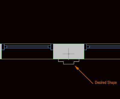
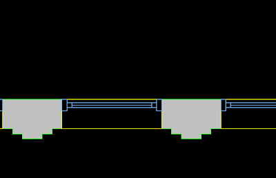
As you see, we have a regular wall and some windows, but we want the space between the windows (what is the name in English for that?) to have the shape of the white line. To do that, we first increase the thickness of the wall to reach the thicker point necessary. THen we select the wall, right mouse click and select Endcaps --> Edit in Place. We will access the endcap edit mode. Endcaps work exactly as AEC Polygons, so take a look at this post on how to edit AEC Polygons. In the image below you can see the endcap after being edited in the Endcap Edit in Place Mode.
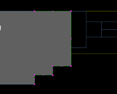
But when we exit, we see that the Window sill is showing like floating (this is because the window sill is showing the actual thickness of the wall). We have to edit the window style to fix this. Right click the window --> Edit window Style (if you just want to edit one window of this style you can pick "Edit Object Display")
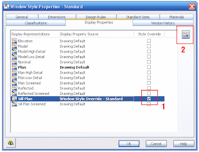
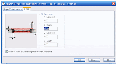
In this dialog, we have to edit the Sill Plan. Click on the box to the right of the Sill Plan and go to Edit Display Properties on the upper right. In the following dialog we need to click the "other" tab. Here is where we will set how much we want the Sill to be recessed from the wall edge to show the way we want it. In our example we need to set the B dimension to -0.10 (negative will make the sill be recessed)
The final result is the desired. See the image below for the final wall with its irregular shape and the sill aligned to where we wanted.
Tweet


No comments:
Post a Comment