The HfT has a repository of all (or most) of the abstracts of the students master thesis available online.Català - Castellano - Deutsch
Not so long ago, I published here the summary of my Master Thesis on the Topic of BIM for Project Management. We have been told today that all abstracts are now available on the School website, so I thought I'd share the link to it so you can see the summary in pdf and properly edited form.
You can see the Abstract of my Master Thesis named "Using BIM as a Project Management Tool - How can BIM help the delivery of complex construction projects" here.
For all the other abstracts, see this page. The quality of the Master Thesis varies as it happens in any course. Two of the ones I know where pretty well done (besides mine ;P) are the ones by Jürgen M. Volm on Risk Management (focused in Germany) and the one from Ralf Schulmeister on how to implement Lean Management in Germany.
Since I posted the summary and references I got a lot of inquiries about the Master Thesis and I am very happy to answer those questions. If you need any help writing or researching a similar topic, please contact me and I'll do my best to guide you on the hard process of academic research.
Cheers.
Show me more...
Presentations of the First Meeting of the Spanish Group for Lean Construction
Now available online the presentations of the first meeting of the Spanish Group for Lean Construction.
English - Català - Deutsch
As I recently published, I recently attended the first meeting of the Spanish Group for Lean Construction. The presentations of this first meeting are now available online.
The two that I found most interesting were undoubtedly the one by Paul Napolitano from General Contractor Herrero of the United States on the theme of the Last Planner System (Last Planner System). A very interesting introduction to this method of collaborative planning. Unfortunately this one is not available online.
The one that you can see online is that of Antonio Rodriguez, from the firm BECS on the same topic. Here are the slides of the presentation (in Spanish).
Show me more...
English - Català - Deutsch
As I recently published, I recently attended the first meeting of the Spanish Group for Lean Construction. The presentations of this first meeting are now available online.
The two that I found most interesting were undoubtedly the one by Paul Napolitano from General Contractor Herrero of the United States on the theme of the Last Planner System (Last Planner System). A very interesting introduction to this method of collaborative planning. Unfortunately this one is not available online.
The one that you can see online is that of Antonio Rodriguez, from the firm BECS on the same topic. Here are the slides of the presentation (in Spanish).
Primera Reunión del SGLC. Antonio Rodríguez
View more presentations from SGLC
Show me more...
Labels:
Lean Construction
Revit: Calculating the weight of structural members (and how to Fix that "Inconsistent Units" Problem)
Calculated values give sometimes "inconsistent units" errors. there is a fix for that of course.
Català - Castellano - Deutsch
I recently blogged about using Revit for Quantity Take Off. One of the things I was mentioning was the need to obtain the total steel weight to be able to estimate the costs of a steel structure. This is how I did it.
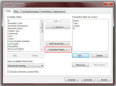
The main idea was to obtain the weight of the steel members. I will use the beams and bracing elements schedule for this example. I had families for the structural members with a weight per lineal meter parameter in them (I introduced that parameter myself from steel catalogs). I still needed to get Revit to calculate the total weight of each element with a fórmula. To do that, we need to add a new column on the schedule with a calculated value (length of the structural element times the weight per linear meter). On the Schedule view, click the Edit button near the "Fields" text in the properties palette. Then you will get a dialog like the one below (I am assuming you already have created a Schedule for Structural Beams and Bracing, and added the W parameter were you have entered the Weight per Linear Meter for each type of structural member).
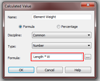
The value we want is a calculated value of the default Length parameter times the W parameter we have created (Weight per linear meter). So we click on Calculated Value and we get the following dialog.
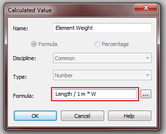
Logic seems to ask for a simple formula like "Length * W", but if we use this formula, we will get an error saying "Inconsistent Units". Well, this point turned me crazy for some hours until I found a solution here. Apparently, since Length has meters as units, you can't get a calculated value unless you "neutralize" those units. The formula in this case to be able to get the calculated value is "Length / 1 m * W". By dividing Length by 1 m, we eliminate the units from the formula and we are able to obtain the much wanted total weight for each element.
After doing this, my structural elements schedule looked like this, ready to be exported with all the information I needed to be able to do some estimations on the building structure (the right colored column shows the weight of each structural member).
Show me more...
Català - Castellano - Deutsch
I recently blogged about using Revit for Quantity Take Off. One of the things I was mentioning was the need to obtain the total steel weight to be able to estimate the costs of a steel structure. This is how I did it.
The main idea was to obtain the weight of the steel members. I will use the beams and bracing elements schedule for this example. I had families for the structural members with a weight per lineal meter parameter in them (I introduced that parameter myself from steel catalogs). I still needed to get Revit to calculate the total weight of each element with a fórmula. To do that, we need to add a new column on the schedule with a calculated value (length of the structural element times the weight per linear meter). On the Schedule view, click the Edit button near the "Fields" text in the properties palette. Then you will get a dialog like the one below (I am assuming you already have created a Schedule for Structural Beams and Bracing, and added the W parameter were you have entered the Weight per Linear Meter for each type of structural member).
The value we want is a calculated value of the default Length parameter times the W parameter we have created (Weight per linear meter). So we click on Calculated Value and we get the following dialog.
Logic seems to ask for a simple formula like "Length * W", but if we use this formula, we will get an error saying "Inconsistent Units". Well, this point turned me crazy for some hours until I found a solution here. Apparently, since Length has meters as units, you can't get a calculated value unless you "neutralize" those units. The formula in this case to be able to get the calculated value is "Length / 1 m * W". By dividing Length by 1 m, we eliminate the units from the formula and we are able to obtain the much wanted total weight for each element.
After doing this, my structural elements schedule looked like this, ready to be exported with all the information I needed to be able to do some estimations on the building structure (the right colored column shows the weight of each structural member).
Show me more...
Labels:
BIM,
Estimating,
Revit
Some basic CAD organization is necessary!!
You can0t work on a project with all your drawings on a single file, seriously, you are not a student anymore, and if you are, better start training for the real world.
Català - Castellano - Deutsch
I am lately working more often with BIM than I am with CAD, but recently opening and analyzing some CAD drawings recieved from an architect made me think about writing this post. The thing is, while there might be no way to organize a CAD (or BIM) project without any flaws, there are some basics that I find essential if you want to keep certain quality standards and ease of use.
If we talk about quality, there is a basic standard people should aim for, and that is about consistency of information between drawings. That is, if two walls are 6,50m apart in one drawing, the same walls should be 6,50m a part in another drawing. Does it sound too basic, well, believe me, I've seen very basic drawings not accomplishing even that. The reasons might be many, but, as I see it, you can't expect quality if you have ALL YOUR PROJECT DRAWINGS ON A SINGLE FILE AND WORK ON THIS SINGLE FILE!!
Sorry for the shouting, but this has been making me waste a lot of time.
Why would you work with all your drawings on a single file? I have no clue other than "because you haven't thought about a better way". Let's ask ourselves a few questions. If we work with all project drawings in one CAD file:
If you are an All Drawings in One File (ADIOF) Architect, maybe you think your projects are small enough to not require a file organization standard, well you are wrong. Any project works better if you split files. My little list for ADIOF Architects of what you could do as a minimum to increase quality and workability of your drawaing standards:
Show me more...
Català - Castellano - Deutsch
I am lately working more often with BIM than I am with CAD, but recently opening and analyzing some CAD drawings recieved from an architect made me think about writing this post. The thing is, while there might be no way to organize a CAD (or BIM) project without any flaws, there are some basics that I find essential if you want to keep certain quality standards and ease of use.
If we talk about quality, there is a basic standard people should aim for, and that is about consistency of information between drawings. That is, if two walls are 6,50m apart in one drawing, the same walls should be 6,50m a part in another drawing. Does it sound too basic, well, believe me, I've seen very basic drawings not accomplishing even that. The reasons might be many, but, as I see it, you can't expect quality if you have ALL YOUR PROJECT DRAWINGS ON A SINGLE FILE AND WORK ON THIS SINGLE FILE!!
Sorry for the shouting, but this has been making me waste a lot of time.
Why would you work with all your drawings on a single file? I have no clue other than "because you haven't thought about a better way". Let's ask ourselves a few questions. If we work with all project drawings in one CAD file:
- What happens if you want to split work amongst two people? You can't.
- How do you check that columns, walls on other buidling elementsare on the same position in all floorplans? Well I assume you basically draw some help lines and go check if they allign, but doing this you only check in one direction...
- What happens if you accidentally delete, loose, can't find or get a Fatal Error on your AutoCAD file? Well, instead of loosing or having to redo information about one floorplan or elevation, you might need to redo stuff in ALL your drawings
If you are an All Drawings in One File (ADIOF) Architect, maybe you think your projects are small enough to not require a file organization standard, well you are wrong. Any project works better if you split files. My little list for ADIOF Architects of what you could do as a minimum to increase quality and workability of your drawaing standards:
- One file, one drawing: Anytime corrections need to be done you could have more than one people working on it
- All floor plan drawings are on the same position in each drawing: this way you can easily use the other drawings as XREFs (External References)to check the consistency between them (the same way you would have done long ago putting one drawing on top of the other using transparent paper)
- Use the same prefix for all files of the same sort (FL for Floor plans, EL for elevations, etc): This way your project folder will be organised by type of drawing.
- Use a single file inserted as an External Reference for those elements such as column grids, elevator cores, stairs, etc that go vertically through the building: instead of modifying those elements once in each drawing, you will save time by changing them once only.
Show me more...
Labels:
AutoCAD
Subscribe to:
Posts (Atom)