Showing posts with label Hatch Patterns. Show all posts

AutoCAD: AutoLISP to Generate Multiple Hatch Boundaries

Do you need to re-generate the boundaries of multiple hatch patterns? An AutoLISP routine will do it.
Català - Castellano - Deutsch
I had to work on some files converted from ArchiCAD to AutoCAD and needed to use the AEC Space entities to get the areas. Unfortunately, plain AutoCAD doesn't read the are of this objects, and by exploding them, it generated Hatch Patters that would not show their area on the properties palette.

The solution for a single AEC_SPACE, was simple, explode it, regenerate the boundary of the Hatch Pattern, and select the resulting Polyline to see the area (or to extract the area to an excel file as explained on a previous post). The problem came becuase there were a lot of this AEC_SPACE objects,and AutoCAD does not allow to regenerate boundaries of multiple Hatch Patterns at the same time.

The solution was found via DigitalCAD, in the form of a LISP routine called HATCHB.LSP. This routine when used, allows you to select as many Hatch Patterns as you want and obtain their boundaries in the form of polylines. The polylines will be generated on the current layer, and properties.

Some thoughts: This real life situation is a clear case that shows how format incompatibilities makes us waste a lot of time. In this case the lead architect works in ArchiCAD, but we as Contruction Managers have only AutoCAD, so everytime we get files from them there is a lot of information in those files that is wasted, because we can not read it properly, so we have to waste hours on retracing polylines to be able to double check the information we have received...


Show me more...

AutoCAD Weekly Block #08: Cobblestone Pattern

Download this block and learn about the SUPERHATCH command
Català - Castellano - Deutsch
This week's Block is the first that is not a dynamic one. The reason for that is that I remembered I had not talked in here about the SUPERHATCH command. As you will see, the SUPERHATCH command allows you to hatch an area with any custom made hatch.
Why is it in the weekly block section? Well the way SUPERHATCH works involves Blocks much more than it involves hatches (it actually does not involve hatch patterns at all.
The block for download is a cobblestone pattern that my company uses in some of the projects (not everyone gets to work on Zaha's futuristic shapes...lol). You can Download it here. See the snapshot of the block below.


We use this block to hatch certain areas, and the way to do it quick and efficiently is using the SUPERHATCH Express Tool. When you call the SUPERHATCH command, you will see the following menu.


Here you will select Block as an option and use the downloaded "CAD-Addict.com cobblestone" Block. After doing this, simply follow the prompts, basically, you simply need to pick the initial position, rotation and scale, and then pick an internal point of the area you want to Superhatch.
The result will be a set of blocks clipped to fit the boundary selected. See below.


Remember that when selecting "internal point" if the drawing is heavy the computer might crash, so I would recommend you to switch off any unnecessary layers before attempting this operation.

This command has more options that have not been explored in this post, but I think you can get an idea of how powerful this is.

Show me more...
AutoCAD: How to Create a Custom Hatch Pattern with Text in it

This how I did it. It was a bit long but it helped me understand what to deal with when creating you own patterns.
Català - Castellano - Deutsch
On my last post, I analysed how the Hatch Pattern files work. How they define the patterns through straight lines and what is the syntax they use. I was not entirely satisfied with all I learned and wrote here so I decided to go from the theory to the practice and try to create my own hatch pattern file.
I decided to not attempt just a random pattern, but one that required certain precision. So I set the goal to create a pattern that would repeat the text CAD-Addict.com. Possible? yes it is.
The process started by creating the text. If you remembered what I wrote on the previous post, a pattern is created by straight lines with linetypes that we can decide that repeat themselves the way we decide to. So how would we do it to show a text on our hatch pattern just with some straight lines? We had to find a way to align the lines of the text on a way that they would repeat themselves in different directions. Let's see an image to understand this.

The text with the C circled in Red is the original one, the ones circled in Yellow are the ones I used to be sure the lines allign. See that this text has only lines at 0 degrees, 90 degrees, 45 degrees and 135 degrees. Alligning the o degree lines it is easy. The important part is to manage to allign the 45/135 degrees and do it in a way that the 90 degree ines also allign. In this case the fact that the tilted lines are 45/135 degrees makes it easy, if the there where other angles it would have been much more difficult. (The original text, created with the standard AutoCAD text style, had the lines on the upper part of the A at a different angle, but I modified that to make the pattern file more easy to create. See in the image below, how with the original text there was no easy way to find common lines for the A.

The process I followed once I had the text aligned is simple. First I started to set up the 0 degree lines (Remember to check the previous post for more details on the syntax of the Hatch PAttern files).Picking the lower left corner of the C as 0,0 point it was all a question of measuring distances. Something you need to know is that linetypes in hatch patterns can only use 6 elements from DASH SPACE or DOT. We define DASH with positive value, space with negative and point with a zero. See the hatch pattern definition of the horizontal lines and you will get a better glimpse of what I mean.

The text highlighted in yellow doesn't belong to the pattern definition, I added it for reference while building the pattern file. As you can see, although all the lower horizontal lines of the letters are aligned, I couldn´t define them in a single line definition because I would have exceeded the maximum of 6 elements for the line type definition.
Lets go back to how the pattern file works. The first number defines the angle of the line, the second and third (the second column) defines the start point coordinates of that line, the 4th and 5th number (3rd column) describe the delta-x and delta-y of the line. This point requires certain attention. Lets take for instance the horizontal lines. The delta-x and delta-y I had to use was -1.0607,1.0607. Lets see graphically what that means.

The last column might have no values at all (if the line is continuous), or up to 6 to define its linetype. For the lower horizontal lines for the letters C, D and d, the pattern file I created describes 0.1,-0.4475,0.1475,-0.7949,0.0508,-2.702 as linetype. THis means 0.1 of dash,0.4475 of space,0.1475of dash,0.7949 of space,0.0508 of dash,2.702 of space. Why is the last space so much bigger than the other ones? Because it describes the distance between the last dash and the first one on the next text. See the image below and compare the dimension values to the first 4 ones above.

The 6th value, on the 4th column, the one that is disproportionately bigger compared to the others, belongs to this dimension.

I after all this information you don't still feel like you could create your won pattern, I can only tell you that the best way is to try to create one. Suddenly all the abstract concepts you are reading will start making sense.
Just a couple of points I discovered while creating the pattern file. Be sure there is at least one blank line at the end of all the definitions, or AutoCAD won't accept the pattern. Also, once you have created the YOURPATTERN.pat file (or while creating it to test it) save it under the following where all the Custom Patterns are in AutoCAD. generally that folder is under C:\Documents and Settings\USERNAME\Application Data\Autodesk\AUTOCADVERSION\enu\Support\pats.
If you want to see or test the pattern definition I created., you can download it here. And below you can see a snapshot of the pattern generated by the file.

I know the pattern is not very useful for everyday life, but creating it was very useful to understand how to create a custom hatch pattern.

Show me more...

AutoCAD: Understanding the .pat Hatch Pattern Files

How do you define a new custom Hatch Pattern? Better understand how the .pat files work.
Català - Castellano - Deutsch
Searching for how to generate custom hatch pattern definitions in AutoCAD i came across this post by Ellen Filkenstein. Although the post gives you an idea on how these pattern definitions work, it took me a while to understand everything. So I went to the acad.pat file and I picked a complicated pattern to see if I could figure out how it works. I chose the AR-CONC pattern. This is a snapshot of it.


The first thing I realized disappointed me. I thought the pattern files could define any geometry, and somehow they do, but it turns out that any geometry created has to be based on straight lines. Let me show you why. Although the AR-CONC pattern seems pretty random, it is not. If you pay attention to it you will see that the triangles repeat themself on straight lines.


So, does the pattern definition describe a triangle and how often should be repeated? Not at all. A more detailed look to the pattern showed me that there is not such a thing as triangles in the pattern, but lines that intersect each other creating triangles (I know, that is the same almost, but not in terms on how you define the patter, see the image below).


So how are this lines defined to end up showing like triangles? Here is the tricky part. See the image below that belongs to the acad.pat definition for the AR-CONC pattern.


There are 4 elements that are important here:
  1. Defines de Angle that the line should take.
  2. Defines the X and Y coordinates of the start point of that line.
  3. Sets de Delta-x and Delta-Y displacements.
  4. Defines the linetype.
Ok, I know, this is textbook theory, I had no idea what this meant after I read about it. So I hatch some region in AutoCAD with this pattern and I searched for a line that was at an angle of 50 degrees. Surprise!! I found one. And suddenly everything made sense. It would take me long to describe it all so I made a quick diagram. See it below. The colors correspond with the numbers of the previous image for easy reference.


See how the angle (red) corresponds with the one described in the pattern file. The start point is 0,0. And here comes the juicy part. In Blue, the linetype. The pattern describes 0.75,-8.25. This means 0.75 units of dash, 8.25 units of space (the negative sign means space, 0 would mean a dot). And finally the file defines 4.12975034,-5.89789472 as Delta-x, delta-y displacement. See it in the picture with the green dimensions.
I guess now we can start defining our own patterns...or maybe not. Sincerely having the SUPERHATCH command available through the express tools, the process of generating your own pattern files seems a bit outdated. Of course the entities created with SUPERHATCH are blocks and not Hatch patterns, so they will give you much less freedom to edit them, so it is your choice to decide which method to use. I will talk soon in a new post about the SUPERHATCH command with more detail.

Show me more...

AutoCAD Architecure: Forget about Associative Hatch Patterns

For a long time I struggled to remember to check the box "Associative" when creating Hatch Patterns. Now I know I don't need to do this anymore.

For a long time I struggled to remember to check the box "Associative" when creating hatch patterns. Without that Box checked it was really hard to modify any existing hatch pattern. But even creating an associative pattern didn't make it very flexible to work with them. A lot of times the boundary bothers us so we end up erasing it and doing that we loose the associativity of the pattern.
AutoCAD Architecture has some features that make hatch associativity something from the past. When we have a Hatch Pattern, we can select it and right click on it. We will get the contextual menu shown on the left side of this post.
The beauty of it is that if we click on generate boundary, an AEC polygon will be generated. We can then modify that polygon to fit our new hatch needs and after that we simply select the Hatch - Right Click - Set Boundary - And we will select the modified polygon. We will we prompt to decide if we want to erase the polygon or not, which I personally recommend say yes, since it is so easy to recreate them.
But this is not all, AutoCAD Architecture has another set of tools that will improve our work flow, the AEC Modify Tools. These tools will allow us to easily modify our hatch by Merging it with other entities, Subtracting parts of it or dividing it in two. I will write a post soon with more details about the AEC Modify Tools.
For those Using classic AutoCAD classic these features are not available. You can Recreate the Boundary of a Hatch by double clicking it and selecting "Recreate Boundary". I don´t think there is anything similar to the AEC Modify tools in the classic version of AutoCAD.
If you are in the AEC industry I seriously encourage you to jump ASAP to AutoCAD Architecture whenever you need to update your CAD software. It boosts the work flow of your employees many times. To learn all the features specific to AutoCAD Architecture you might want to buy this book.

Show me more...

AutoCAD: Disabling selection preview for Hatches

Do you get stuck in the selection preview of complex objects?A nice feature like the selection preview can become really annoying if we are working with dense hatch patterns.
What selection preview does is that it highlights the object we are going to select if we click the left mouse button. This works very nice and smooth with simple objects like lines, polylines, arcs, etc. It happens though that when we have a dense hatch, specially if it is a hatch made of dots it might take several seconds to show the selection preview due to the amount of objects in the hatch pattern.
Although we can turn off the selection preview turning the SELECTIONPREVIEW system variable to 0, what we actually want to do is to keep it on for some elements and off for some others like hatch patterns.
We have two options to do that.
  1. Set the system variable PREVIEWFILTER to 16, this will only exclude hatch patterns from the selection previews.
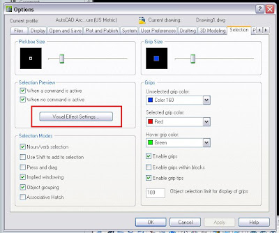
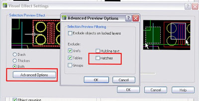
  2. Go to Format --> Options --> Selection Tab -->Visual Effects Options --> Advanced Options --> Uncheck the Box in front of Hatch Patterns.
See it in a couple of images for more detailed reference.


Show me more...

AutoCAD: Adjusting Hatch Density

Sometimes when we want to create a hatch that is too dense we get the following message: "Hatch spacing too dense, or dash size too small." This means that we are trying to create a hatch that is denser than the maximum allowed by the system. This might be changed with a simple procedure. We type the following on the command line bar:(setenv "MaxHatch" "10000"). 10000 is the default value, so it will actually not change anything. If we want to create a hatch and we get the sentence mentioned above, we must increase the maximum density allowed. That means we must type for instance: (setenv "MaxHatch" "10000000"). By changing 10000 for 10000000 we increased the maximum density allowed in the drawing. Try to create the hatch gain, it will work this time. If it doesn´t enter the command again with a higher value till it allows you to create the hatch.

Command line order: (setenv "MaxHatch" "10000000")

Show me more...