Showing posts sorted by relevance for query ellipse. Sort by date Show all posts

AutoCAD: Dealing with Ellipses

Ellipses are necessary but troublesome. Learn to deal with them appropriately.
Català - Castellano
If you have a Boss like mine who loves ellipse shaped Buildings, Drop-offs, Piazzas, etc. you probably have to deal with ellipses more than you wish. Ellipses are quite troublesome.
First of all they don't offset as ellipses, rather when we offset an ellipse the parallel geometry obtained is a SPLINE. Splines have the disadvantage that they can only be trimmed but not extended.

One way to partially solve this problem is to know the PELLIPSE system variable. The default value of this paramter is 0, which means ellipses are drawn as ellipses. If we set it to 1, instead of an ellipse the geometry drawn is a POLYLINE. The advantage of using polylines is that they can be exploded (Ellipses can't) and when offset they remain polylines. Another advantage is that Polylines can be converted to other types of objects (in ACA you can convert them to Walls, Spaces, etc).
The disadvantage of drawing ellipses as Polylines is that since they are an approximation of an ellipse made with multiple curved segments, if we trim part of the ellipse shaped polyline we will probably not going to be able to recover the old geometry by using the extend command.
Another consideration when deciding if you want to set PELLIPSE to 1 or 0 is to think if you will need to modify that ellipse often. If you will be trimming and extending segments of an ellipse my recommendation is to keep it in 0 (the ellipse is a "smart object" you will be able to recover all of its geometry from its smallest segment if is a real ellipse, if it is a polyline yo will have to redraw it) If you will be offsetting the ellipse better set it to 1 so you avoid getting Splines that will leave you with no flexibility.
Another issue I found when dealing with ellipses is when I want to redraw one that is not aligned with the active UCS. For some reason the "UCS Object" feature doesn't allign properly with the axis of ellipses. So, if you want to draw an ellipse using the same alignment for its axis as a previous one this is what you need to do.
You need to know the concept of Quadrant Osnap. In ellipses (and circles) quadrant osnap is a point on the ellipse that intersects the ellipse axis. See the three images below for a clearer explanation (click on the image to enlarge)

The image on the left shows a selected ellipse. The grips we see correspond to the centre and quadrant osnaps of the ellipse that we will use to get the righ UCS alignment. The image in the middle shows how we can access the Osnap contextual menu to select the quadrant osnap. (follow this link for more info on the topic). The image on the right shows the line from quadrant to quadrant drawn. We will use the align UCS to Object to this line to get the correct UCS that will allow us to redraw an ellipse equal or parallel to the original one.(This only works with Ellipses drawn with PELLIPSE = 0).

Show me more...

AutoCAD: Offset Ellipses and keep them as Ellipses

Tired of getting SPLINES when you offset you ellipses? Maybe you want to try this quick video tutorial.
Català - Castellano - Deutsch
One of the biggest issues of working with ellipses is the fact that if we offset them using the OFFSET command, they become Splines. Splines are entities that are hard to work with, especially when we need to trim parts and later we want to extend them again. Tired of toggling the PELLISPE system variable many times, i wanted to see if there was a way to offset an ellipse but keep it as an ellipse. I did found the way to do it. It is a bit slower than using the OFFSET command, but if you think you might need to edit the resulting ellipse maybe you want to give it a try. See the video below.


The steps are simple:
  1. Draw two lines from the quadrants of the ellipse. Their length should be the distance you want to offset the ellipse. (To be able to Snap on the qadrants, turn them or access the quadrant osnap with through the OSNAP contextual menu)
  2. Select the ellipse, move one of the grips next to one of the lines to the other end point of that line while holding the CTRL key.
  3. Move the grip next to the other line you previously draw to the other endpoint of the line
That´s it, your resulting parallel ellipse is still an ellipse and not a SPLINE.


Show me more...

AutoCAD: Meet the OSNAPs

Have you ever wondered what does each and every Osnap do? I did, and I tried to find out.
Castellano - Català
On my personal experience and according to what colleagues and friends tell me, it seems that none of us takes full advantage of all the OSNAPs available in AutoCAD. I
think the way we work is mostly based on the way we always did, so we tent to not try new things, we like routine.
Once said that, I must admit that many times discovering a good way to use some of the OSNAPS makes your work flow improve considerably. So it is worth trying all of them and seeing what can they do to improve your AutoCAD proficiency. As a way of self discovering some of the OSNAPs I never use, and to share those that I think are the most useful, here is a compiled list of them with some quick description of what are they for and how they improve your drafting experience.
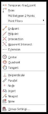
First a quick tip for those who don't know this. If you press Shift+Right Click on the drawing space, a contextual menu with the list of OSNAPs will appear ( See this previous post for more information about this). We will use this contextual menu (the picture on the left) as a list to describe each Osnap individually. The letters between parenthesis are the text entry/shortcut for those Osnaps
  • Temporary Track Point (tt): If for any reason you like to work with Object Snap Tracking (OST) not active, this OSNAP will allow you to track from one point you select. It has a weird behaviour I have to say, because it seems not possible to use it twice in a row (I need to investigate more because so far it doesn't make sense)
  • From (from): It allows you to click on a point and set the distance from that point you want to start or finish drawing. Almost impossible to use accurately if OST is Off, unless you use relative co-ordinates. It is actually useless in most situations because OST already allows you to do most of what "from" does (if someone knows any other use of this please don't hesitate to collaborate)
  • Mid Between two points - (m2p): My favourite one, it allows you to snap on a point exactly in the middle of two given points. Very very useful and quite unknown since it doesn't appear in the Osnap Settings Dialog Box.
  • Point Filters (.x .y .z): For those who used Microstation and miss that pressing the space bar to lock one of the Axis, this will make the trick. We can, for instance select to lock X, select the X coordinate that we want locked, and then choose any point. The resultant point will have the X we locked using this Osnap and the X and Z of the last selection. It can combine multiple axis locked, XY, XZ, YZ.
  • Endpoint ( end ): One of the most basic ones. Not much is needed to mention since normally everyone works with this one permanently active. It will snap to one of the endpoints of an object, showing a square sign.
  • Midpoint (mid): Another of the classics, it snaps to the midpoint of an object, it shows the triangle sign.
  • Intersection (int): It snaps to the intersection of two objects. The objects need to have a real intersection, if no intersection is found between two objects that apparently are intersecting, check the Z values of this objects, since one or both might be not on Z=0. The sign is the X
  • Apparent Intersection (app): What the previous osnap doesn't find as an intersection this one will. According to the active view it will ind the visual intersection between two objects. The sign is a square with an X inside.
  • Extension (ext): It will let you choose any point on the extension of an arc or line.
  • Centre (cen): Points to the center of an arc, circle or ellipse. The marker is a circle.
  • Quadrant (qua): Points to 4 Points on a Circle or Ellipse. These 4 points depend on how was the UCS when this geometry was drawn and will always follow the direction of this original UCS. They would be the North South West and East coordinates of an Arc or Ellipse, being North where the Y axis is pointing. In Arcs or Portions of Ellipse they behave as if the Circle or Ellipse was complete, but only those that fall on the arc or portion o ellipse will be selectable. The sign is a square tilted 45 degrees.
  • Tangent (tan): Allows to draw lines tangent to circles, arcs or ellipses. It doesn't work if we are drawing an arc. The sign is a circle with a line.
  • Perpendicular (per): Finds the point that makes the line you are drawing perpendicular to the geometry you want. It can be used with lines, arcs, circles and ellipses. The sign is like an inverted T.
  • Parallel (par): Only for lines. It allows you to draw a line parallel to another one. It is less intuitive to find out how to use it. You must select the first point, then chose Parallel Osnap if it's not permanently active, point on the line you want the new one to be parallel to. A Double line sign appears, then move the cursor away to where the parallel line should be. A dotted line appears and the parallel Osnap marker shows on the original line, click a second point.
  • Node (nod): To snap on points or nodes. If you draw points using the POINT command, the only way to Snap o them is using "node" osnap. Also, when you use MEASURE or DIVIDE, points (nodes) will appear on the object (unless you use the [Block] option). The sign is a circle with an X.
  • Insert (ins): With this object snap you can point to the insertion points of objects like Blocks or Text. The sign is a shape consisting of two squares.
  • Nearest (Nea): Not to be used if you are trying to be precise, this osnap will select the closes point on an object, it can be useful for quick drawings and measurements, but it shouldn't be used for drawings requiring precision.
  • None (non): If at some point we need to select a point and we don't want to use any osnap we can select the None Osnap that will turn them all off for one click. It would be the equivalent of pressing F3.

Show me more...

SketchUp: Drawing Torus, Spheres and Ellipses

Drawing Spheres, Torus and Ellipses is quite easy. There are some plugins though that make it even easier.
Català - Castellano - Deutsch
Some basic shapes like a Sphere, a Torus or an Ellipse are not included in the default tools in SketchUp. They all can be done quite easy without the need of a Plugin, but of course anything that speeds up the modleing process is more than welcome.

Here you can see a quick video showing how to model a Sphere, a Torus and an Ellipse in SketchUp with the standard tools.


As you can see, it is a pretty simple process. Still, some of you might want to have these tools directly accessible on the Draw menu. For this, Regular Polygon has created several Plugins, simply click on the links below to access the Plugin website and to download them.
They also have two plugins called Superellipse and Supperellipsoid (Sort of rectangle with rounded edges, or cube with rounded edges) for this one I don't see a some way to draw it easily with the standard tools, so here comes the link to the two of them.


Show me more...

AutoCAD: LISP Routine for Converting Splines to Polylines

A LISP Routine to Convert some SPlines to Polylines. It has some bugs though.
Català - Castellano - Deutsch
I was recently looking for a way to convert Splines to Polyines and found a LISP routine via Cadalyst. The routine works fine for Splines that we create from scratch. Unfortunately it doesn't work properly for Splines that have been generated when we offset an ellipse. In that case, the resulting polyline does not correspond to the spline we selected. For any other spline, it seems to work properly. You can download it at the cadalyst website.
As I previously explained, remember that you have the option to create ellipses as such or to do it creating an ellipse looking polyline through the PELLIPSE system variable.

Update: Kerry pointed out that there is a much easier way to convert Splines into Polylines. It is as simple as using the FLATTEN command for the spline you want to Convert. Thanks Kerry for the feedback.

Show me more...

SketchUp: List of Plugins

Find here all the SketchUp Plugins that have been listed on CAD-Addict.com
Català - Castellano - Deutsch
This is the up to date, list of all the SketchUp Plugins I´ve talked about in CAD-Addict.com (it will be updated in the future as soon as new Plugins are added as new posts)
  1. ARTMINE: Allows you to import more than 5000 pieces of art to your sketchup model
  2. BEZIER (bezier.rb): creates Bezier curves
  3. CADSPAN: Makes your model 3D print ready and exports to STL format.
  4. CAMERA RECORDER (clf_camera_recorder.zip): Records your camera movements and exports a set of images to be able to create a walkthrough animation.
  5. CLEANUP (tt_cleanup.rb): excellent Plugin to clean geometry, unnecessary coplanar edges and other features.
  6. COLOR BY SLOPE (clf_color-by_slope.rb): Colors faces according to their angle
  7. COLOR BY Z (clf_color_by_z.rb): Colors Faces according to their Z value (height)
  8. COMPONENT STRINGER (clf_component_stringer.rb): Places components along a path, with several options of scaling and rotation.
  9. CUBIC PANO OUT (cubicpanoout.rb): exports 6 images to generate a 360 degrees quicktime panorama.
  10. DELETE COPLANAR EDGES (deletecoplanaredges.rb): Removes unnecessary edges between coplanar faces.
  11. DROP (drop.rb): Drops groups/components till they intersect with the model, ideal for site modeling.
  12. ELLIPSE ( rp_ellipse_v12.rb): Allows you to draw ellipses
  13. ENGINEERING TOOLBOX (EngineeringToolbox.rb): Allows you to place standard beams, ducts, elbows, etc.
  14. EXTRAPOLATE COLORS (lf_extrapolate_colors.rb):paints a bunch of faces randomly allowing you control on the colors used.
  15. EXTRUDE EDGES BY EDGES (extrudeEdgesByEdges.rb): to extrude a curved edge along a curved path.
  16. EXTRUDE EDGES BY FACE (ExtrudeEdgesByFace.rb): An easie to use follow me Tool. Extrude a face along a path without the need to align that face with it.
  17. EXTRUDE EDGES WITH ROTATION (ExtrudeEdgesByLathe.rb): Extrudes rotationg the edges or the face a certain angle around a given axis.
  18. EXTRUDE EDGES BY RAILS (extrudeEdgesByRails.rb): Extrudes an edge following to given rails.
  19. EXTRUDE LINES (extrudelintool.rb): extrudes lines using a vector.
  20. FLATTERY (flattery.rb): An upgraded unfold tool, to turn your 3D model into a 2D unfolded model ready to be cut in paper and glued together.
  21. FLIGHT PATH (flightpath.rb): Allows to generate the scenes of a flythrough animation by selecting a path.
  22. FREE SCALE (FreeScale_Tool.rb): Aligns the Scale Box to any line on the drawing.
  23. GEOMETRIC CURVE SMOOTHING (crvsmth.rb): Edit Curves
  24. GREEBLE 2 (clf_greeble_2.rb): Allows you to add random, and not so random, complexity to your geometry.
  25. GRIDS (grid.rb): to create parametric grids.
  26. HELIX (drawhelix13.rb): Draws a helix or a spiral
  27. HOVER SELECT (HoverSelect.rb): Select or deselect edges by click and drag.
  28. INSTANT ROAD (InstantRoad.rbs): Creates roads quick and easy
  29. INSTANT ROOF (InstantRoof.rbs): Creates pitched roofs with just a few clicks
  30. JOINT PUSH PULL (JointPushPull.rb): Allows you to Push Curved Faces.
  31. LATICEIZER (Laticeizer.rb): creates a window with its mullions and glass parts from a series of faces, cleaning up the intersections very neatly
  32. LINES TO TUBES (lines2tubes.rb): turn a bunch of lines, arcs, circles, curves, etc into cylinders.
  33. LOFT (clf_simple_loft.rb): Creates a simple loft between two or more profiles.
  34. MAKE FACES (makefaces.rb): Generates all possible faces from selected geometry.
  35. XD MAKE FUR (fur_en_v1_2.rb): A Plugin to generate Fur / Grass with a lot of control.
  36. MIRROR (mirror.rb): Mirror objects selecting a mirror plane.
  37. MODELFUNCTION (Modelfunction.exe): Sort of explicit history (primitive grasshopper) for SketchUp, very promising
  38. OFFSET ON SURFACE (OffsetOnSurface.rb): Allows you to offset curved faces.
  39. ONION DOME (oniondome.rb): to create onion shaped domes.
  40. ONTIME 5D (ontime5d.rbs): easily simulate the construction process (virtual scheduling or 4D modelling) for free.
  41. PAGE EXPORT IMPORT (PageExIm.rb): Allows you to export pages to be imported to another model.(not free)
  42. PLUGIN LOADER (as_pluginloader.rb): Loads plugins without restarting SketchUp.
  43. ROTATED RECTANGLE (rectangle.rb): creates rotated rectangles.
  44. ROUND CORNERS (RoundCorner_Tool.rb): Turns sharp corners into round ones.
  45. SCALE ROTATE MULTIPLE (clf_scale_rotate_multiple.rb): Randomly Scale and rotate objects, ideal for Vegetation / Site Design.
  46. SECTION CUT FACE (SectionCutFace.rb): Fills the section cut with a face.
  47. SELECTION HIDE/SHOW (SelectionHideShow.rb): Adds contextual menu options to show hide selections in many different ways.
  48. SHAPE BENDER (clf_shape_bender.rb): to Bend an object to follow the profile of a curve.
  49. SHAPES (shapes.rb): to create and editing a number of parametric shapes.
  50. SIMPLIFY CONTOURS (SimplifyContours.rb): it simplifies the geometry, making it easier to work with.
  51. SLICER (slicer.rb): Creates slices from your model.
  52. SMART PUSH PULL (a4_smartpushpull.rb): Pushes faces considering the contiguous oblique faces.
  53. SOAP SKIN BUBBLE (SoapSkinBubbleTools.rb): Creates tensile like structures.
  54. SPHERE (rp_sphere_v11.rb): Models spheres
  55. STRAY LINES (stray_lines.rb): Deletes lines that do not generate faces.
  56. SUPERELLIPSE (rp_superellipse_v12.rb): A superellipse is a shape that is in between an ellipse and a rectangle.
  57. SUPERELLIPSOID (rp_superellipsoid_v10.rb): Creates a shape between a round shaped ellipsoid and a square shaped rectangular box.
  58. XD SYNCRO PROJECT CONSTRUCTOR (price $800): allows you to simulate the construction process (virtual scheduling or 4D modelling). It's more a stand alone program rather than a plugin.
  59. TORUS (rp_torus_v10.rb): Creates Torus and Twisted Torus.
  60. TUBE ALONG PATH (TubeAlongPath.rb): turns connected line paths into cylinders.
  61. UNFOLD TOOL (jf_unfoldtool.rb): Unfolds a model to a flat set of faces.
  62. VERTEX TOOLS (price $20): Performs all sort of operations with vertex. Equivalent to 3D Max Soft Selection feature.
  63. VOLUME CALCULATOR (VolumeCalculator21.rb): to calculate volumes of objects.
  64. VRAY: Creates realistic renders from SketchUp (not free).
  65. WEB EXPORTER (Sketchup6webexporterwen.exe): allows you to export a model to be published on web.
  66. WELD (Weld.rb): Welds lines into polylines.
  67. WINDOWIZER (windowizer.rb): Creates Windows with multiple options.
  68. WINDOW MAKER (windows.rb): creates parametric double-hung and slider windows.
  69. XD VIRTUAL BUILDER (price $59): allows you to simulate the construction process (virtual scheduling or 4D modelling)
  70. 1001BIT TOOLS (1001bit_tools.rbs): a full set of tools for Architecture to build your buildings way faster(not free).
  71. 3D to PDF (price $95): Converts your sketchup model into a 3D Pdf to easily share your models


If you are new to Ruby Scripts, check this post on How to Install SketchUp Plugins.

There are other online resources to find Ruby scripts online. Some of the best online libraries where you can find and download SU Plugins are, as far as I know:


Show me more...

AutoCAD: Use Curved Frames to Clip your References

Clip your Blocks or XREFs using curved polylines, circles, etc
Català - Castellano - Deutsch
A common problem found when using the XCLIP command is that it doesn't clip properly if the polyline we use has curved segments. The same way we can't use circles to clip Blocks or XREFs. If you try to clip a block using a polyline that contains curved segments you will see that along the curved segment the clipping is not done properly. See the following image. The block was clipped using the yellow polyline. The result is not satisfactory at all.


The first image shows the original block, the second one is the block clipped with the XCLIP command. As you see we need a work around this result. The work around is to use an Express Tool Command.

CLIPIT is an express tool command that will allow us to do what we wanted to do. CLIPIT will ask us to select the new clipping frame, that can actually be a POLYLINE, CIRCLE, ARC, ELLIPSE, or TEXT object. It works the opposite as the XCLIP command. With CLIPIT you first select the frame and then the Block, Image, Wipeout or XREF you want to clip. See the following image with the result.


What CLIPIT does, is turn the curved clipping frame into a set of segments. If you switch on the XCLIPFRAME and select the block, you will see that the frame is actually made of straight lines. See it below.


The only bad part of this express tool, is that so far (till version 2009) it doesn't allow inverted clips. We talked about how useful inverted XCLIPS can be on a previous post. Hopefully in future versions of AutoCAD this will be solved.

Show me more...

AutoCAD: List of 2D Objects

A complete and Organized list of the AutoCAD 2D Objects and links to those explained in CAD Addict.
Català - Castellano - Deutsch
There are many different types of Objects in AutoCAD. On an effort to keep updating the directory of CAD-Addict.com here comes a complete list of the 2D Objects and the links to those articles that explain their use. I will try to keep adding lists of objects weekly and at the end I will create a post that works as a main directory for this series of posts.
2D Objects

There are 2D objects that are created through other commands, but regardless when created they are in one of these categories. An example of this would be Polygons, Rectangles or Donuts which are actually Polylines.

Show me more...

AutoCAD: Select all Connected Geometry.

Wonder how to select with a single click all connected geometry? AutoCAD can do it, you just need to know the right command.
Català - Castellano - Deutsch
Usually my day at work involves designing and drawing both in AutoCAD and SketchUp (and eventually in Rhino depending on the complexity of the geometry of the project). Switching back and forth from one software to another makes you miss on one program some of the functions that the other program has. This was the case of the "Select all Connected" option in SketchUp. It is so useful to select all connected geometry (it can be accessed through a right click menu or by triple clicking any line on the drawing). But can something similar be done in AutoCAD? The answer is yes.

There is an Express Tool for AutoCAD called FASTSEL (accessible also via the FS shortcut) that allows us to select all the geometry that is connected (touching) any element on our drawing. The elements that can be used using this commands are LINE, POLYLINE, LWPOLYLINE, CIRCLE, ARC, ATTDEF, TEXT, MTEXT, ELLIPSE, SPLINE or IMAGE objects. BLOCKS or XREFs containing these objects will also work.
AEC Objects from some of the vertical products such as Walls or AEC Polygons are not supported. In case you have a Block or XREF containing both supported and unsupported elements, the command will only use the supported elements.

The command can be accessed transparently while using other commands by typing 'FS while the command is running. Also, use the FSMODE System Variable to control if the FS command selects all connected geometry (FSMODE = ON) or only the geometry connected to the first object (FSMODE = OFF).

Note that this Express Tool Command is mostly intended for 2D since I tried to use it in 3D and lines that are actually not touching other geometry did get connected. I find it specially useful when I accidentally explode polylines, with this command you can select all the lines that where previously connected with a single click. Select faster than a private jet with this express tool!

Show me more...