Showing posts sorted by relevance for query text autocad texts. Sort by date Show all posts

AutoCAD: Text Express tools

One of the treasure of latest AutoCad versions are the express tools.
Català - Castellano
In some versions of AutoCAD, you have to check the box that asks you to install them when installing the program, but believe me, they are worth it. Simpler ways to do things com with the express tools.
Lets analize those Express tools that helps us improve the way we treat Text.
We have:
ARCTEXT (Express - Text- Arc aligned Text)
With this one we can place a Text following the path marked by an ARC. We have several options on how to do it to select from the ArcAligned Text Workshop dialog box.

We can select to justify text on either side or center of the arc or to fit it along the length o the ARC. We can place it on the outer part of the Arc or the inner one, Upside down, reverse other, etc. Regetfully this tools don't seem to suport a curved path created by a polyline. Just as a quick example of what you would get check this image.


TEXTFIT ( Express - Text - Text Fit)

We can take any text (not multiline text) and shrink it or stretch it to fit in any given dimension. See that this is basically a fastest and more visual way to play with the widht factor of the text.
See this three texts, each of them shrunk to fit in different lentgh but keeping the same text height.

TXT2MTXT
We can convert any TEXT or DTEXT into MTEXT.

The Upper text was transformed into the lower Mtext with the TXT2MTXT command.
The remaining Express Tools for Text I don´t really find them that Useful or I haven´t been using them so I´ll simply list them here. They are:
TEXTMASK Masks entities from behind text
TEXTUNMASK Remove mask from text
TJUST Changes a text object's justification without changing its position. Works with text, mtext, and attribute definition objects.
TORIENT Aligns text, mtext and block attribute objects to new orientation
TSCALE Scales text, mtext, attributes and attribute definitions.

Show me more...

AutoCAD: Using Annotative Scale for Texts

Annotative Scale Texts are an awesome way to speed the annotation process when a drawing needs to be shown in different Scales.
Català - Castellano - Deutsch

Since AutoCAD 2008, there is a property for several entities called Annotative Scale. What this property allows us is to show the objects differently according to the Active Annotation Scale. This is specially useful for Text notes.

Imagine a floor plan of a project shown at 1:200 scale with a lot of descriptive notes. The notes you have will be the right size to be printed at 1:200. But you might want to use the same drawing to show an enlarged plan of certain portion of the project. The problem is that if you just blow it up, the notes will be twice the size that shows "properly" when printed. Annotation Scale will help you solve this.

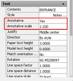
If you select the text and go to the properties Tab, there is a property called "Annotative". By default this is set to NO. Change it to YES to turn the Text into an Annotative one. There is a system variable, ANNOAUTOSCALE, that controls if new annotation Scales are added automatically or not, it has a lot of values, from -4 to 4, so see here what each value does.

In general, it is not recommended to have the ANNOAUTOSCALE set to automatically add annotation scales to all the objects, since that would increase the file size quite a lot. Alternatively, set the annotation Scale of the drawing by selecting it on the lower right side of the screen.


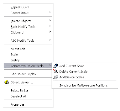
Then, you can simply select those objects you want to add new annotative scales too, right click --> Add Current Scale.


One more thing you can do is set different orientation for each annotative scale. This is very useful, because you might have an overall plan aligned to the World UCS (or North on top, or whatever) and then enlarged plans aligned according to the portion of the building/project you are focusing on. If you rotate the Text using the ROTATE command, it will rotate all its Annotative instances. If alternatively, you select the text, and on the properties tab you enter a new rotation, the new orientation will apply only to the current Annotative Scale. See the following image.


The 1:200 text is aligned in one direction, while the 1:100 text (the smaller one) is aligned according to the enlarged plan orientation. I am still trying to figure out how can I in AutoCAD Architecture, do the same for Space Tags. Will definetily post it whenever I find the way.

Annotative Scale applies to other AutoCAD objects such as Blocks, I will deal with that in a different post soon. Stay tuned

Show me more...

AutoCAD tutorial: Creating a dynamic block 1.0

Learn step by step how to create a dynamic block.
Català - Castellano
Dynamic blocks are a very important resource to increase productivity. What would require several different blocks can be achieved with a single dynamic one if we know how to give the right editing properties to them.
In this first tutorial we will create a dynamic block for an escalator. The block will be able to be stretched to have different step widths, overall lengths (to cover different floor to floor heights) and some other cool properties.
First of all we have to create a standard block. I got the escalator DWG from Schindler, the block is good enough for the precise height you request it. This is the drawing we will start with.
We will name this block Dynamic Escalator. To make this block a dynamic block we have to add Parameters and Actions to the block. To do so, select the blog and type BE (Block Editor). Inside the Block Editor you will find a series of buttons that will allow you to do that.

We have to plan what we want to do, and probably you will have to do things twice or trice till you make the block work as you want. To start we will set the parameters and actions that will let us modify the step width of the escalator. This are the steps we will follow.
  • Click the parameter button
  • Select Linear as Parameter Type.
  • Select the two edges of one of the steps.
  • Choose to show only one grip.
This is how the parameter should look after we created it.

Now, we need to add an action to this parameter. This are the steps to follow.
  • Click the Action Button
  • Select the Parameter
  • Choose Stretch As the Action Type
  • Select the Grip
  • Select the stretch Polygon (like you would select the objects using the STRETCH command)
  • Select the objects to be stretched.
The block should resemble to this:
Try to save and go out of the block editor. Check that the block behaves the way it is expected. If it does we will continue adding parameters and actions.
Next we will make the block stretchable in length. This will require more than one action since we not only want to stretch the lines, but also make extra steps appear when we stretch the block.
We will do the following:
  • Add a linear parameter to the length of the block
  • Add a stretch action to stretch all the lateral lines of the escalator.
  • Add an Array action to make new steps when the block is edited.
The first think we will have to do is to erase all the step lines except one so we can use the array action properly. With that done, we add a linear parameter to the length of the block. See that I also added some markers on a non plot layer so I know certain points where the length of the escalator corresponds to certain floor to floor height (like 5m, 6m, 7m etc.). The block should look something like this at this point (inside the Block Editor Interface):


We want the step lines to show all the way from end to end of the escalator. We need to add an array action to the same linear parameter that we are using for stretching the block in length. We follow these process:
  • Click the action Button
  • Select the linear parameter.
  • Choose Array as the action
  • Select the single step line we have when prompted to select objects
It is important that the linear parameter starts on the step line and ends where the steps are supposed to disappear, otherwise you might get step lines out of the boundaries they are supposed to be. Again, save the block and go out of the block editor interface. Check that the parameters and actions added work as desired.
We still want to add a couple more parameters to the block. First we want text and an arrow that shows if the escalator is going down or arriving from the level below. We will use the text DN for going down, and AR for an escalator that arrives to the level we are showing. First we prepare the block for the actions we want to add.
  • We type both texts AR and DN on the same exact position.
  • We mirror the arrow head so we have a line with arrows on both sides.
It should look like the image above. What we want to do is to be able to use the same block either for an elevator going down (DN text with the arrow pointing away form the text) and an elevator arriving to the level we are showing (AR text with the arrow pointing to it). We will have to use a different parameter type called Visibility. It is important to know the buttons related to the visibility parameter. They are situated on the upper right corner of the block editor interface. They are the following.

  1. Toggles objects on other visibility states on and off.
  2. Makes an object visible in the current visibility state
  3. Hides an object form the current visibility state
  4. Calls the visibility states dialog box (where we will create different visibility states)
So the steps we will follow are:
  • first we have to do is click button #4 and create a new visibility state called AR, and rename the existing one as DN.
  • Having DN as active visibility state select the AR text and the arrowhead pointing to it and click button #3 to hide them. (the objects will diappear if you didn't click button #1, if you did the objects will be faded)
  • Turn AR visibility state active, select DN text and arrowhead pointing away from it and hide them (button #3)
Let's check if it worked. Save the block and get out of the BE interface. Select the block and click on the grip corresponding to the visibility parameter. You'll be able to select the visibility mode you want so with the same block you will be able to show both an escalator going down and another arriving to the level we are. See the too pictures below.

The last edit I added to the block is a rotation aprameter and action that allows me to rotate the text to any position I want. The idea is that no matter in which angle the escalator is placed, the text should always be facing the right way. See the image below to understand what I mean..
I am not going to detail the steps for this since it is pretty simple and similar to the rest of the process. Just think of using a rotation parameter and action applied to the center of the text.
If you want to check the escalator file, you can download it here.

Show me more...

AutoCAD Find and replace text

Find and replace texts in your CAD File. no need to enter edit each one of them
Català - Castellano - Deutsch
. Well, first of all, hi everyone. It's been almost a year since I posted. My current job doesn't bringing me so many new insights on CAD or BIM tricks lately, so unfortunately, I am a bit dry on new tricks. Nevertheless I still have to draft in CADevery now and then and so I lately discover this little basic trick that was very useful for a last minute change without a lot of pain.
We were about to send a set of drawings to the Millworker for quoting a job and last minute,"the boss" said, change grom Viroc to Valchromat, I told you I wanted to use Valchromat. Ok, so last minute and all the notes in all the Milwork elements needed to be changed. There were abotu 20 different elements with many notes each that needed changing, so I decided I 10 minute search was worth the effort to save maybe 30 minutes of manually changing texts. And it did pay off quickly.
Can't remember now were I found it but the solution was simple, use the FIND command in AutoCAD. It basically has the same or almost the same functionalities as the Find and Replace user interface in Word or similar text prcessors. So changing all those notes took basically less than a minute. Simply type FIND, enter the text to replace in the FIND box and enter the new text you want in the REPLACE box. Very simple. It works both for TEXT and MTEXT characters.
Hope to write more if I get a chance! THanks a lot for all the comments the blog keeps getting despite my partial absence!


Show me more...

AutoCAD: Control How You Mirror Texts

Do you want to Mirror Text but AutoCAD keeps it the same way? There is a system variable for that.
Català - Castellano - Deutsch
The System Variable MIRRTEXT controls how texts are mirrored. The default Value 0, mirrors the location of the texts, but it does not actually mirrors their orientation. If you set the value of MIRRTEXT to 1, then you will be able to Mirror the Text or Mtext as if it was any other object, Block, etc. Chek the image below. First is a text mirrored with the MIRRTEXT system variable set to 0, the second one has the variable set to 1.


Show me more...

AutoCAD: Switch Text Between Uppercase and Lowercase

Did you forget the Caps Lock on while typing a long text in AutoCAD? Don't delete it, do this.
Català - Castellano
Some people type texts staring at the keyboard instead of at the screen. That together with the fact that sometimes we forget the Caps Lock on, means that we end up deleting and retyping some texts. No need to retype anymore.
If we select the text we want to turn from uppercase to lowercase and press together CTRL + SHIFT + L, it will automatically become lowercase.
The system works too on the other way. If we press CTRL + SHIFT + U, the selected text will turn to uppercase.

Show me more...