AutoCAD Weekly Block #01: Dynamic Wardrobe

A Wardrobe Block 60cm deep that can adopt any length.
Català - Castellano - Deutsch
I am going to start sharing weekly some of the Blocks I've been creating for some of our projects. Some of them, like this one, will help us go through some of the basics on how to deal with Blocks. In this case, we will quickly go over how to create a Dynamic block again (there is a longer post from some months ago explaining in more detail How to Create a Dynamic Block).

Download the Block or see the image of the below.
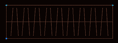

As you can see in the image, the block shows two arrows on its upper corners. These are the Grips that allow us to modify it's length. If you enter the Block Editor (select the Block and type BE) you will see something like this.
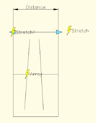
Lets see what each of the elements found does. Distance is teh Linear Parameter, it defines a distance that can be modified. Stretch is an Action. Actions associated to parameters is what creates the interactivity on dynamic blocks. The stretch and stretch1 action stretch the wardrobe on its length. The other element is Array. Array is another Action, and what it does is to repeat the two tilted lines when the block is stretch.
The process to create this block is simple. Once we have the basic linework that you see inside the Blockeditor (the outline and the two tilted lines) we do the folowwing:
  • We create a Block out of this line work with origin on one corner.
  • Enter the Block Editor, BE (do not edit block in place with REFEDIT command)
  • We add a Linear Parameter from one corner to the other.
  • To add the array action, click the actions button, select the distance parameter and enter array as action type. Then select the 2 tilted lines as objects and enter the distance you want the copies to appear my block uses 0.2m, but you can set it to anything you want)
  • Now we add the Stretch Action. Again click the Actions button, select the Distance Parameter, Select Stretch as type of action, select one of the Distance parameter points, Draw a Polygon as you would do usng the STRETCH command and select the objects you want to Stretch. (be sure to avoid selecting the tilted lines)
  • Do the same for the other side of the wardrobe with a new Stretch Action.
That´s it. You have created a dynamic Block. Try how it behaves. Remember that I will be sharing more blocks regularly. You can subscribe to the blog feed to not miss any of them, or just come by often.

Show me more...

AutoCAD: Using an Excel Sheet as if it was an XREF

You can insert an Excel sheet in AutoCAD and keep it linked so when the sheet is updated, it shows the updates in AutoCAD
Català - Castellano - Deutsch
Many times, we use MS Excel (or similar)to show area charts, parking counts, unit types, etc. For a long time I had been printing the Excell Sheets to PDF format, turning them nto JPEGs and then inserting them as images in AutoCAD. BEsides being a 3 step process, it has the disadvantage that whenever the worksheet was updated, the process needed to be done again and again.
I just discovered recently that there is no need to Print as PDF and insert an Excel Sheet. It can be inserted in a way that it will remain linked and it will update. And it is much simpler than you think.
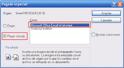
Simply select the part of the sheet you want to insert in Excel, press Ctrl + C (or Edit --> Copy). Then, go to the AutoCAD drawing you want to insert it in an go to Edit --> Paste Special. You should see a dialog like the one below.

On the left side, select "Paste Link", and from the options offered on the right side, select "Microsoft Office Excel Worksheet". That's it, almost as simple as Copy and Paste with just a few extra tweaks, and it will save you lots of time. ANytime you save the Excel Sheet it will automatically update in AutoCAD.

Show me more...

2008 Top Ten Visited Posts

The ten favourite posts by the users in 2008 by the number of Unique Visitors
Català - Castellano
Sorry for the almost two weeks of silence, I've bee out of town and then very busy. Till I get some time to organize myself here comes something I wanted to do for a long time. The list of the 10 most visited posts in 2008. I have my own favourite list that I will share soon, but this is your list, the posts that you have found more useful. The list belongs only to the English version of CAD Addict. The other languages have their own lists.
  1. SketchUp Plugins: Weld
  2. SketchUp Plugins: Extruding and Offsetting Curved Faces
  3. AutoCAD: How to Create a Dynamic Bloc
  4. AutoCAD: Overkill and Flatten Commands
  5. AutoCAD: List of Express Tools
  6. SketchUp: VRAY for SU works on version 7 too
  7. SketchUp: Bonus Packs and Extra Materials
  8. AutoCAD: THings That Shift Can do For You
  9. SketchUp Plugins: Volume Calculator
  10. SketchUp 7: New Features and Download Link


Show me more...

SketchUp 7 for Dummies

A new book of the series "For Dummies" has been released for version 7 of SketchUp
Català - Castellano
Wiley Publishing has released a new SketchUp for Dummies book to explore the new SkechUp 7 version. According to Wiley's description with this book you will "start creating models right away" and you can learn to:
  • Set up SketchUp, learn about edges and faces, use inferences and guides, and build your first model
  • Establish a basic end-to-end workflow for creating and sharing models
  • Model non-boxy objects like terrain, characters, bottles, and spheres
  • Add details like stairs, gutters, and eaves
  • Spruce up your models with styles and shadows to add effects, make objects pop, and enhance realism
  • Use the LayOut function to draw with vector tools, add text and callouts, and print your work
  • Design buildings and objects, export your models to other design programs or to Google Earth, and explore 3D animation
There are some new sections on the book compared to the previous release covering new features and previously omitted tools:
  • a brand new section on the Sandbox tools
  • a brand new section on modeling organic shapes with the Scale, Push/Pull, and Follow Me tools
  • a brand new section on Dynamic Components, including how to use them and how to create them
  • coverage of the new photomodeling tools
  • a revised chapter on LayOut 2


or


Show me more...

AutoCAD: Single or Multiple Windows

You might want to keep all open files in a single window or have multiple ones. There is a system variable to tweak this.
Català - Castellano
The system variable TASKBAR allows us to control if all files show in a single window or on multiple one on the windows task bar. Setting it to 0 will make all files to show on a single element on the task bar, setting it to 1 will show each file as a individual element.
Both with the setting on 0 or 1 you can toggle between files pressing CTRL + TAB or going to the Windows drop down menu and selecting the file you want to see.
I personally use the setting on 1 because I like to switch between files by pressing the corresponding window o the task bar, but each person has a different preference so it is good to know how to switch between the two display modes.

Show me more...

Rhino: Importing AutoCAD Aliases

You can use some of your AutoCAD aliases in Rhino. It just needs some minor adjustment.
Català - Castellano
First thing I missed when starting to use Rhino was being able to draw a line by typing "L" or copying an object by typing "C" (I use C for copy in AutoCAD). I thought I had to get used to the new aliases till Chaitanya told me I could get my AutoCAD aliases in Rhino.
To import aliases to Rhino we need to have them stored in a .txt file, and go to Tools --> Options --> Aliases.
See that you can't directly use your acad.pgp. I tried to simply change the .pgp extension to .txt, but the formatting of the AutoCAD aliases doesn't match the requirements of Rhino. We can very quickly reformat the file though, by erasing all the introduction, and erasing the comas and the asterisks.
Take into consideration that many AutoCAD commands don´t apply to Rhino, so it is wise to create your own .txt file with only those Aliases from CAD that you find indispensable to have available in Rhino. Slowly as you see which Rhino commands you use more often you can keep adding aliases to your aliases file to match your requirements.
You can download my acadtorhino.txt file, it is a quick file that can be used to import the basic ACAD aliases to Rhino (see that a couple of them like C for COPY and R for ROTATE are not AutoCAD standards, but my standards, but you can modify them easily if you are a 2 letter typer)

Show me more...

AutoCAD:Explode Unexplodable Blocks

Do you find yourself unable to explode certain Blocks? Don't despair, the solution is easier than you might think.
Català - Castellano - Deutsch
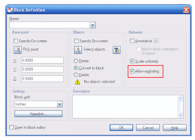
When a Block is created there are several options that sometimes are overlooked. One of this is the option to not allow the block to be exploded. If you don't know that this exists, you might find yourself unable to explode a block that you really, really, really need to explode (I am no fan of Block exploding, I mostly hate people who do that as a hobby, but sometimes you do need to explode them).
The trick is to open the block definition dialog box (type "b", or "block") without selecting anything. Then on the drop down list search for the block you are unable to explode. You will see that the "allow exploding" option is unselected. Select it and click OK. Now select the Block, enter X for EXPLODE. The Block should explode.
As I said before, be careful about exploding blocks (specially in a multiuser environment). If they have been created as blocks is for a reason, so exploding them might screw up someone else's effort. Remember that Blocks can be scaled, clipped using the XCLIP or CLIPIT commands, etc so consider other options before exploding them.

kick it on CadKicks.com

Show me more...

Rhino: Easy Creation of Curved Windows and Store Fronts

Creating curved Windows and store fronts might be tedious in other programs. Not in Rhino. You just need to know the right command.
Català - Castellano
Do you manually model all the curved parts of your buildings? Stop doing so. Rhino can do it for you. Let's imagine that we want to draw a curved window. We could create the curved mullions, glass, etc, or we can simply use the FlowAlongSrf command. Let me show you what this command does.
We will try to make a curved storefront following a given curve, divided in 4 parts vertically and 5 horizontally. Instead of trying to manually model it we create a flat version of it. See the image below.

To make the final result easier to handle, be sure that you Group the Storefront Mullions together. Once you have them grouped, you need to extrude the curve to the height you want the store front to be. After that you need to create a plane that matches the size of the flat store front that you have created. Something like the image below.

After we have this, everything is ready. Select the flat storefront. Type FlowAlongSrf. Select the plane near the flat storefront as base surface and select the curved surface as the target surface. These are the results.

The command FlowAlongSrf really makes modelling of curved façades much easier. See some other examples of what you can achieve with it, both based on the same 5 x 4 module.

Thanks to Chaitanya for teaching me today this.


Show me more...

AutoCAD: Dealing with Ellipses

Ellipses are necessary but troublesome. Learn to deal with them appropriately.
Català - Castellano
If you have a Boss like mine who loves ellipse shaped Buildings, Drop-offs, Piazzas, etc. you probably have to deal with ellipses more than you wish. Ellipses are quite troublesome.
First of all they don't offset as ellipses, rather when we offset an ellipse the parallel geometry obtained is a SPLINE. Splines have the disadvantage that they can only be trimmed but not extended.

One way to partially solve this problem is to know the PELLIPSE system variable. The default value of this paramter is 0, which means ellipses are drawn as ellipses. If we set it to 1, instead of an ellipse the geometry drawn is a POLYLINE. The advantage of using polylines is that they can be exploded (Ellipses can't) and when offset they remain polylines. Another advantage is that Polylines can be converted to other types of objects (in ACA you can convert them to Walls, Spaces, etc).
The disadvantage of drawing ellipses as Polylines is that since they are an approximation of an ellipse made with multiple curved segments, if we trim part of the ellipse shaped polyline we will probably not going to be able to recover the old geometry by using the extend command.
Another consideration when deciding if you want to set PELLIPSE to 1 or 0 is to think if you will need to modify that ellipse often. If you will be trimming and extending segments of an ellipse my recommendation is to keep it in 0 (the ellipse is a "smart object" you will be able to recover all of its geometry from its smallest segment if is a real ellipse, if it is a polyline yo will have to redraw it) If you will be offsetting the ellipse better set it to 1 so you avoid getting Splines that will leave you with no flexibility.
Another issue I found when dealing with ellipses is when I want to redraw one that is not aligned with the active UCS. For some reason the "UCS Object" feature doesn't allign properly with the axis of ellipses. So, if you want to draw an ellipse using the same alignment for its axis as a previous one this is what you need to do.
You need to know the concept of Quadrant Osnap. In ellipses (and circles) quadrant osnap is a point on the ellipse that intersects the ellipse axis. See the three images below for a clearer explanation (click on the image to enlarge)

The image on the left shows a selected ellipse. The grips we see correspond to the centre and quadrant osnaps of the ellipse that we will use to get the righ UCS alignment. The image in the middle shows how we can access the Osnap contextual menu to select the quadrant osnap. (follow this link for more info on the topic). The image on the right shows the line from quadrant to quadrant drawn. We will use the align UCS to Object to this line to get the correct UCS that will allow us to redraw an ellipse equal or parallel to the original one.(This only works with Ellipses drawn with PELLIPSE = 0).

Show me more...

AutoCAD: Muiltiple XREF repath - The Reference Manager

AutoCAD Installs an external application that allows you to repath multiple XREFs.
Català - Castellano - Deutsch
The Reference Manager is a utility introduced in AutoCAD 2004 that is not very well known since it is external to AutoCAD itself. The purpose of it, as it name states, is to Manage the External References.
To access it you need to go to Start --> Programs --> Autodesk --> AutoCAD 20XX --> Reference Manager.
The interface is pretty simple. The main use I found for it is to re-path XREFs that have been moved to different folders. You cans elect all the XREFs that need re-pathing, right click on them and click "Edit Selected Paths". See the image below.
The Reference Manager allows you to Manage any file that a drawing uses as a Reference, such as plot style tables, Fonts, Images and XREFs. Being Images and XREFs the ones that most commonly are misplaced, this are the types of files that you will most commonly re-path through the Reference Manager.
Re-pathing is something that you can do in AutoCAD using the XRef Manager, the Image Manager, etc. But when a file that was referenced in 100 drawings has been chenaged of location, you don;t want to enter those 100 drawings and repath this XREF in each one. The Reference Manager allows you to do this for the 100 drawings in a few clicks.
What I miss in the Reference Manager is the option to not only repath (choose the folder of the XREF) but also choose a new XREF. Sometimes the broken path is due to a change on the name of a file rather than a change of location. It would be great if the Reference Manager allowed us to point multiple files to the new XREF.

kick it on CadKicks.com

Show me more...

Rhino Plugins: Block Editor

Rhino does not have Block Editor by default, but there is a plugin for that.
Català - Castellano
If you start using Rhino like me coming from an AutoCAD, Microstation and/or SketchUp background you'll be used to create Blocks, Cells or Components, to edit them later.
Rhino by default does not have a Block Editor so you might find yourself a bit lost if you imported a file in Rhino from other applications that work with Blocks or similar entities.
No problem. Rhino, very similarly as SketchUp, has a wide range of Plugins to enhance its functionality. One of this is the Block Editor plugin, that will add the needed functionality to your Rhino. To download it go to this link. The Mcneel website has plenty of information about how to install plugins.
You need to use the PlugInManager command to load the Plugin, browse to the location where you have the plugin stored and click OK. After that you can select a block and run the command InPlaceBlockEdit to edit the block.
To manage Blocks Rhino has the BlockManager that allows you update and delete existing blocks and linked files.

Show me more...

Follow CAD Addict on Twitter

Now you can follow CAD Addict also on twitter
Some months ago I started to use twitter. Since it seems to be working pretty good and I keep getting new followers almost every day I thought I'd share with everyone the possibility to follow the posts directly from your Twitter account. To do so, follow this link and click follow, if you don't have a twitter account you'll have to register first.
Remember that you can also subscribe to the RSS feed using the links on the upper right corner of the CAD Addict website.
For those using Facebook, I also created a page through NetworkedBlogs application.

Show me more...