Job Directory

This is the CAD Addict Job Directory. Visit often for more Job opportunities.
We have partnered with Workcircle to provide a comprehensive data base of TOP Jobs in different countries. You can check some of the Jobs listed in the different categories/regions or use the Search Box at the bottom of the screen to search for a job. We will continue to search for the best resources to provide Job opportunities in these difficult moments.

Job Type: Architect

Job Type: CAD Related


Show me more...

AutoCAD: Do You Want to use it on your Mac?

Do you want to be able to use AutoCAD in your Mac without having to install Windows? Tell Autodesk About it.
Català - Castellano - Deutsch
Autodesk has started a Survey to know if its worth developing the new version of AutoCAD to be usable in the latest Mac operating systems. I do not use Mac but if any of you do, probably you are using Parallel Desktops or something similar to run Both the Mac OS and Windows. Well that might change if enough people show their interest. The survey not very long so if you are a MAC user, better put 5 minutes into it!
Some months ago I wrote a post about what to do if you wanted to run AutoCAD without windows. The only solution available by then came from a comment by e2002 who said he was able to run AutoCAD in Linux with overall good performance.
Maybe soon the MAC community will be able to do that to...Or maybe some of us will switch to MAC?

Show me more...

AutoCAD Weekly Block #02: Dynamic Dinning Table

Download this Block and learn about Standard Sizes for Dynamic Blocks
Català - Castellano - Deutsch
Last week I started the Weekly Block section with a Dynamic Wardrobe block and a tutorial on how to use the Stretch and Array Actions.
This week´s block is a Dinning Table block. You can download it here. The block is dynamic too, so it can be transformed from a dinning table for 4 people to a table for 6, 8, 10 or 12 people.
To do that, I used a Linear parameter and Stretch and Array actions. Since I already explained on last week's post and on a previous one how to use these features, I am going to skip this explanation today.
What we will focus today is on how to set standard sizes for dynamic blocks. Once we have the Block set with the parameters and actions associated working properly we want to limit how the block can be modified.
In our example, we want the length of the table to change in increments of 0.80 meters. What we have to do is the following. Being in Block Editor mode, select the distance parameter you want to set standard sizes to. On the properties palette go to Value Set --> Distance Type and select List.

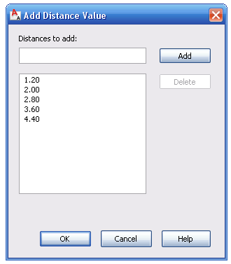
After that we need to add the values the list. Click on the 3 dots on the right of the "Dist Value List" Box. A dialog opens like the one below where you can add the list of values you want the distance parameter to take.

The 1.20 value is there because it is the value of the distance parameter when we created it. We will add the values 2.00, 2.80, 3.60 and 4.40. Now, you can exit the block editor and test the block. You will see that when you select the grip to stretch the table, some markers appear on the screen showing you the possible sizes coming from this list that we created.
Since we set the Array column offset distance to be also 0.80m any time we change the length of the table we will see some extra chairs appearing.
The great thing of dynamic blocks is that if used smartly they can simplify things a lot. Before you probably had a Block for a table sitting 4 people, another for a table sitting 6, another for a table sitting 8 etc. Now, you only need one configured like this one and it will work for all them.
Download the Block Here

Show me more...

AutoCAD Architecture: Irregular Walls - Endcap Tutorial

Learn how to use Endcaps. They are very useful when you want your wall openings to be more than just a square.
Català - Castellano
We have been designing a "not very modern" type of building (to say something) in the office. One of the things we have to deal with is the fact that this Gothic-Art Decoish building will have heavy pilasters on the façade to resemble some sort of old architecture.
In previous phases of the project we had been just using regular walls and adding the extra depth of the pilasters with an AEC polygon. Since we were printing with both wall boundary and wall hatch in black, that worked good enough for representation, but it was a pain in the ass when editing the wall, moving windows,etc.
On the current phase, we are reverting to a different kind of representation following more the standards set in the office. This means black boundry line + grey hatch for the wall. The problem is that if we use a regular wall and we add a AEC Polygon to the outside of it to get the extra thickness needed, we will see the line separating the wall and the AECP, and we do not want that.
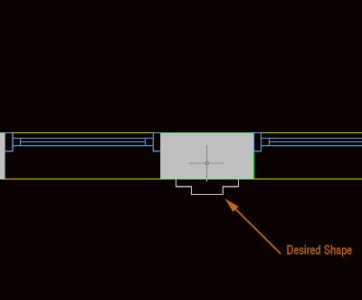
The solution I found for this problem is to use the Wall Endcaps. But let´s start first with a picture of what we want to achieve.


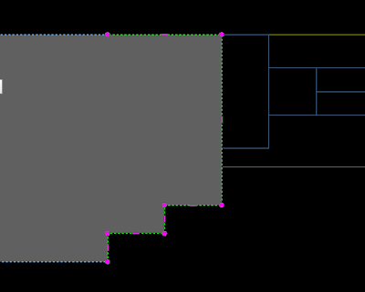
As you see, we have a regular wall and some windows, but we want the space between the windows (what is the name in English for that?) to have the shape of the white line. To do that, we first increase the thickness of the wall to reach the thicker point necessary. THen we select the wall, right mouse click and select Endcaps --> Edit in Place. We will access the endcap edit mode. Endcaps work exactly as AEC Polygons, so take a look at this post on how to edit AEC Polygons. In the image below you can see the endcap after being edited in the Endcap Edit in Place Mode.


But when we exit, we see that the Window sill is showing like floating (this is because the window sill is showing the actual thickness of the wall). We have to edit the window style to fix this. Right click the window --> Edit window Style (if you just want to edit one window of this style you can pick "Edit Object Display")


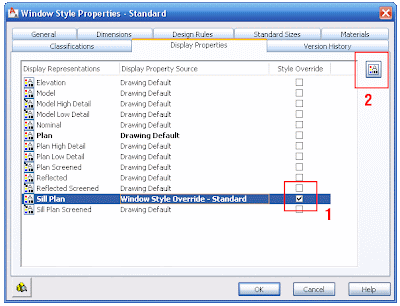
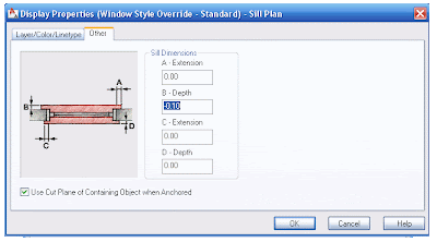
In this dialog, we have to edit the Sill Plan. Click on the box to the right of the Sill Plan and go to Edit Display Properties on the upper right. In the following dialog we need to click the "other" tab. Here is where we will set how much we want the Sill to be recessed from the wall edge to show the way we want it. In our example we need to set the B dimension to -0.10 (negative will make the sill be recessed)


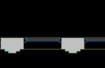
The final result is the desired. See the image below for the final wall with its irregular shape and the sill aligned to where we wanted.


Show me more...

SketchUp Plugins: Delete Unnecessary Lines

Imported drawings can have a lot of unnecessary lines, there is a plugin to remove them all with a single click.
Català - Castellano
When we import CAD drawings to generate 3D geometry from them we might end up with hundreds of lines that we don't really need. Cleaning up the drawing of unnecessary lines is important to work more efficiently, but it can be tedious sometimes.
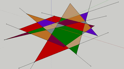
A Plugin that helps a lot on this task is the Stray_Lines.rb Plugin. With this plugin we can either Delete, Isolate (meaning hiding the rest of the model), Label or Select all the lines in a model that have an open end (and thus are not being used to generate a face). See the image below, where we have a bucnh of faces and lines that are not needed.


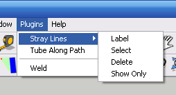
TO get rid of those lines, we could manually erase them. In this case it wouldn't take long, but imagine that instead of 10 lines like here we had 100 or 1000. So what we have to do is simply go to Plugins --> Stray Lines --> Delete. And it will delete any line with an open end.


See in the image that there are 4 options total. Each of them useful in a way or another. Try them out. You can download the Plugin here.

Show me more...

SketchUp Plugins: Make Faces from lines

Learn about a Plugin that will allow you to generate faces from existing linework. Català - Castellano - Deutsch The Plugin Makefaces.rb allows us to generate a face or multiple faces from existing linework. It is very useful both to generate faces but also to know how clean our geometry is. It is very simple to use. Once installed, simply select the lines and go to tools --> Make Faces. If there are any possible faces to be created from the selected lines it will create them, giving you at the end a report of how many faces it has generated. I use it quite a lot, I even have a shortcut for it (CTRL + M). Download it here and give it a try. You will need to download this Script too: Progressbar.rb This is an old post from 2009. you might want to check other Sketchup related posts.
Show me more...

AutoCAD Weekly Block #01: Dynamic Wardrobe

A Wardrobe Block 60cm deep that can adopt any length.
Català - Castellano - Deutsch
I am going to start sharing weekly some of the Blocks I've been creating for some of our projects. Some of them, like this one, will help us go through some of the basics on how to deal with Blocks. In this case, we will quickly go over how to create a Dynamic block again (there is a longer post from some months ago explaining in more detail How to Create a Dynamic Block).

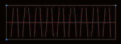
Download the Block or see the image of the below.


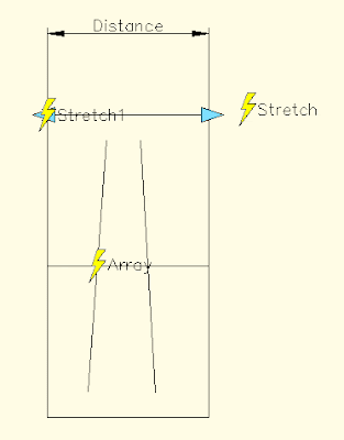
As you can see in the image, the block shows two arrows on its upper corners. These are the Grips that allow us to modify it's length. If you enter the Block Editor (select the Block and type BE) you will see something like this.

Lets see what each of the elements found does. Distance is teh Linear Parameter, it defines a distance that can be modified. Stretch is an Action. Actions associated to parameters is what creates the interactivity on dynamic blocks. The stretch and stretch1 action stretch the wardrobe on its length. The other element is Array. Array is another Action, and what it does is to repeat the two tilted lines when the block is stretch.
The process to create this block is simple. Once we have the basic linework that you see inside the Blockeditor (the outline and the two tilted lines) we do the folowwing:
  • We create a Block out of this line work with origin on one corner.
  • Enter the Block Editor, BE (do not edit block in place with REFEDIT command)
  • We add a Linear Parameter from one corner to the other.
  • To add the array action, click the actions button, select the distance parameter and enter array as action type. Then select the 2 tilted lines as objects and enter the distance you want the copies to appear my block uses 0.2m, but you can set it to anything you want)
  • Now we add the Stretch Action. Again click the Actions button, select the Distance Parameter, Select Stretch as type of action, select one of the Distance parameter points, Draw a Polygon as you would do usng the STRETCH command and select the objects you want to Stretch. (be sure to avoid selecting the tilted lines)
  • Do the same for the other side of the wardrobe with a new Stretch Action.
That´s it. You have created a dynamic Block. Try how it behaves. Remember that I will be sharing more blocks regularly. You can subscribe to the blog feed to not miss any of them, or just come by often.

Show me more...

AutoCAD: Using an Excel Sheet as if it was an XREF

You can insert an Excel sheet in AutoCAD and keep it linked so when the sheet is updated, it shows the updates in AutoCAD
Català - Castellano - Deutsch
Many times, we use MS Excel (or similar)to show area charts, parking counts, unit types, etc. For a long time I had been printing the Excell Sheets to PDF format, turning them nto JPEGs and then inserting them as images in AutoCAD. BEsides being a 3 step process, it has the disadvantage that whenever the worksheet was updated, the process needed to be done again and again.
I just discovered recently that there is no need to Print as PDF and insert an Excel Sheet. It can be inserted in a way that it will remain linked and it will update. And it is much simpler than you think.
Simply select the part of the sheet you want to insert in Excel, press Ctrl + C (or Edit --> Copy). Then, go to the AutoCAD drawing you want to insert it in an go to Edit --> Paste Special. You should see a dialog like the one below.
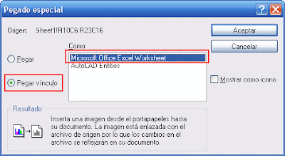
On the left side, select "Paste Link", and from the options offered on the right side, select "Microsoft Office Excel Worksheet". That's it, almost as simple as Copy and Paste with just a few extra tweaks, and it will save you lots of time. ANytime you save the Excel Sheet it will automatically update in AutoCAD.

Show me more...

2008 Top Ten Visited Posts

The ten favourite posts by the users in 2008 by the number of Unique Visitors
Català - Castellano
Sorry for the almost two weeks of silence, I've bee out of town and then very busy. Till I get some time to organize myself here comes something I wanted to do for a long time. The list of the 10 most visited posts in 2008. I have my own favourite list that I will share soon, but this is your list, the posts that you have found more useful. The list belongs only to the English version of CAD Addict. The other languages have their own lists.
  1. SketchUp Plugins: Weld
  2. SketchUp Plugins: Extruding and Offsetting Curved Faces
  3. AutoCAD: How to Create a Dynamic Bloc
  4. AutoCAD: Overkill and Flatten Commands
  5. AutoCAD: List of Express Tools
  6. SketchUp: VRAY for SU works on version 7 too
  7. SketchUp: Bonus Packs and Extra Materials
  8. AutoCAD: THings That Shift Can do For You
  9. SketchUp Plugins: Volume Calculator
  10. SketchUp 7: New Features and Download Link


Show me more...

SketchUp 7 for Dummies

A new book of the series "For Dummies" has been released for version 7 of SketchUp
Català - Castellano
Wiley Publishing has released a new SketchUp for Dummies book to explore the new SkechUp 7 version. According to Wiley's description with this book you will "start creating models right away" and you can learn to:
  • Set up SketchUp, learn about edges and faces, use inferences and guides, and build your first model
  • Establish a basic end-to-end workflow for creating and sharing models
  • Model non-boxy objects like terrain, characters, bottles, and spheres
  • Add details like stairs, gutters, and eaves
  • Spruce up your models with styles and shadows to add effects, make objects pop, and enhance realism
  • Use the LayOut function to draw with vector tools, add text and callouts, and print your work
  • Design buildings and objects, export your models to other design programs or to Google Earth, and explore 3D animation
There are some new sections on the book compared to the previous release covering new features and previously omitted tools:
  • a brand new section on the Sandbox tools
  • a brand new section on modeling organic shapes with the Scale, Push/Pull, and Follow Me tools
  • a brand new section on Dynamic Components, including how to use them and how to create them
  • coverage of the new photomodeling tools
  • a revised chapter on LayOut 2


or


Show me more...

AutoCAD: Single or Multiple Windows

You might want to keep all open files in a single window or have multiple ones. There is a system variable to tweak this.
Català - Castellano
The system variable TASKBAR allows us to control if all files show in a single window or on multiple one on the windows task bar. Setting it to 0 will make all files to show on a single element on the task bar, setting it to 1 will show each file as a individual element.
Both with the setting on 0 or 1 you can toggle between files pressing CTRL + TAB or going to the Windows drop down menu and selecting the file you want to see.
I personally use the setting on 1 because I like to switch between files by pressing the corresponding window o the task bar, but each person has a different preference so it is good to know how to switch between the two display modes.

Show me more...

Rhino: Importing AutoCAD Aliases

You can use some of your AutoCAD aliases in Rhino. It just needs some minor adjustment.
Català - Castellano
First thing I missed when starting to use Rhino was being able to draw a line by typing "L" or copying an object by typing "C" (I use C for copy in AutoCAD). I thought I had to get used to the new aliases till Chaitanya told me I could get my AutoCAD aliases in Rhino.
To import aliases to Rhino we need to have them stored in a .txt file, and go to Tools --> Options --> Aliases.
See that you can't directly use your acad.pgp. I tried to simply change the .pgp extension to .txt, but the formatting of the AutoCAD aliases doesn't match the requirements of Rhino. We can very quickly reformat the file though, by erasing all the introduction, and erasing the comas and the asterisks.
Take into consideration that many AutoCAD commands don´t apply to Rhino, so it is wise to create your own .txt file with only those Aliases from CAD that you find indispensable to have available in Rhino. Slowly as you see which Rhino commands you use more often you can keep adding aliases to your aliases file to match your requirements.
You can download my acadtorhino.txt file, it is a quick file that can be used to import the basic ACAD aliases to Rhino (see that a couple of them like C for COPY and R for ROTATE are not AutoCAD standards, but my standards, but you can modify them easily if you are a 2 letter typer)

Show me more...