Table of Contents

The CAD Addict Blog Directory
Català - Castellano - Deutsch


Show me more...

AutoCAD Weekly Block #06: Dynamic Graphic Scale

Download this Block and learn a bit about Visibility states in Dynamic Blocks
Català - Castellano - Deutsch
This week's Block is a Graphic Scale created as a dynamic block that will be fit for the following scales: 1:50, 1:100, 1:200, 1:500 and 1:1000. The block is meant to be used on paper space. Download the block or see the image below.


The Block is created using a visibility state for each scale, so only the text that fits that scale will show. On the previous image you can see how if you click on the triangular grip of the bock, the different visibility states are shown.
The process of creation is simple. Once you have the linework and text for one of the scales, create the different visibility states for each of the scales. Copy the text and change it values to the one that fits the next scale and hide hat text on the scale you don't want it to be shown. Repeat the process for each scale you want to create. For more details on how to create and modify visibility states check this older post. To summarize what it is important check the buttons related to visibility states in the Block Editor and what they are for. They are situated on the upper right corner of the block editor interface. They are the following.

  1. Toggles objects on other visibility states on and off.
  2. Makes an object visible in the current visibility state
  3. Hides an object form the current visibility state
  4. Calls the visibility states dialog box (where we will create different visibility states)


Show me more...

Rhino: What to Do if Make2D Runs out of Memory?

If you are trying to turn your Rhino model into a 2D drawing but your computer crashes, you might want to try this work around.
Català - Castellano - Deutsch
I was recently trying to extract 2D linework from a very large 3D model in Rhino to be used in AutoCAD drawings, but no matter what I tried, either the result was not the expected or the computer crashed in the process.
What I tried first was the Make2D command, but the computer "ran out of memory" so Rhino crashed. (see that I was doing this on a 8core, 3Gb of RAM computer, so its not an old and slow machine).
Then second option I tried was to Export to AutoCAD and then try to use the FLATSHOT command, but for some reason, the geometry exported to AutoCAD was not suitable for this command. I tried to Export from Rhino to 3Ds to import it in AutoCAD, but again Rhino would crash.
So I found myself without options involving a direct transfer. The only solution I found was to Print the view on hidden line in Rhino to a PDF with big quality, and then convert that PDF to a DXF using a PDF to CAD converter. The one I used is this one, the free trial allowed me to do what I wanted, and the results are better than using the Make2D command from Rhino.

Show me more...

SketchUp Plugins: Unfold your model

Do you need to build a paper model of your Sketchup Model? There are Plugins to Unfold the model.
Català - Castellano - Deutsch
If you want to build a physical model of your SketchUp model, you can do it using the Unfold.rb Plugin. This free plugin can be downloaded here and what it does is exactly what its names says. It unfolds the faces of a model to a plane that you decide.
It is a bit tricky to use, and you have to plan ahead if your model is complicated to be sure that the faces are build in a way that can be unfold. But once you get the sense of how it works you will be able to "deconstruct" your model to transform it in a series of faces laying on the same plane. See the following video for a quick reference on how to do this.


There is also a commercial plug-in called Waybe that automates this process to a single click, but it sells at $50, which I find way overpriced.

Show me more...

Rhino Plugins: Paneling Tools

This is an awesome Plugin to create panels on NURBS surfaces. Another Rhino Beauty.
Català - Castellano - Deutsch
PanelingTools.rhp is an awesome plugin for Rhino to Panel surfaces. You can use the standard Paneling options provided with the Plugin, or generate custom Panels from any shape. The Plugin can be downloaded from the McNeel website. See this tutorial video on how to use Paneling Tools.


After you are done learning the basics, take a look at this other video on how to use the panelling tools with custom shapes.


Show me more...

AutoCAD Weekly Block #05: Dynamic Door

Download this Block and learn about Flip Parameters.
Català - Castellano - Deutsch
On this week's Block we will quickly see how to use the Flip Parameters/Actions. To do that we will use a block of a 80cm door, which in metric unit system would be the most common door you would need to use.
What we want to achieve adding the flip parameters is to be able to flip the door to open to one side or the other without the need to actually using the MIRROR command. So basically we need to add two flip parameters, one to flip the door to open right or left and another one to flip the door to open in or out. Download the block and you will see what it can do.

As you can see in the image above, when the block is selected it shows two arrows. This two arrows allow us to flip the block. But lets quickly see how this arrows work. If we enter the Block Editor, this is what we see.

What I have done is to create two Flip parameters (Flip State and Flip state 1 on the image) following the two perpendicular axis of the block. Then, I added a flip action to each of those parameters, and selected the door and the arch as objects. Nothing else, simple but effective. Of course if you are a user of AutoCAD Architecture this block is useless, but for those using plain AutoCAD this might be useful.

Show me more...

AutoCAD: Layer Creation Script

Learn how to edit a script to re-create all you standard layers
Català - Castellano - Deutsch
Having your standard layers is basic for easy printing and having everyone in the same office know which layers to use for each object. The creation of standard layers and plot tables can be long but it is important if you are trying to set your own standards for several projects.
Some layers are deleted when using commands like PURGE. To get them back there are several methods. One of them is to have a Script that creates all the layers again. This sample script will generate only 3 layers, but it is useful to see how this type of script works. To test the script, save it to your hard drive and type SCR in AutoCAD. Then Browse to the folder where you have saved it and select it. The syntax of the script is as follows:


What you see after ;;; signs is pure description. The script consists of 3 lines. It calls the -LAYER command (See that it uses the hyphen version of the LAYER command, so it does not call the Layer manager window). After each -LAYER there is MAKE to create a new Layer. Then each of the properties of that layer are set.
Following the syntax of this Script with the properties of your standard layers you can generate a script that will allow you to quickly recover all the layers that have been deleted. Here is the link to the Script again.

Show me more...

AutoCAD: My non Sandard Aliases (or why you Should not use Icons)

This are the Aliases I have modified to work the way I like it. I barely need to use any icons.
Català - Castellano - Deutsch
I am a 95% command line AutoCAD user. With that I mean that when I work, I only use icons for 5% of the commands. TO be sincere I think the only reason why I still use those icons, is because I´ve been lazy to set up an ALIAS for them.
The question of using icons or entering the commands with the keyboard seems just a question of taste, but it is not. It is a question of speed. If you want to work fast, forget about using Icons, you should use keyboard commands. The work speed you can achieve having one hand on the keyboard and the other on the mouse is at least 5 times faster than if you have to move the cursor every time to click on an icon.
With that said, some everyday commands have no short alias to make them easy to access, that is why you might need to create your own aliases for those actions you use everyday aften.
For me, there is certain amount of commands I use everyday enough to need a short Alias. For me a good alias is either a single letter or two letters close to each other. THis makes those commands really quick to use, and your fingers soon remember where the letters are so you don't even need to look at the keyboard to enter them. This are the ones I modified in my acad.pgp file (remember that you can easily modify this file with the ALIASEDIT express tool)
  • C, *COPY: just thing of how many times you draw circles and how many times you copy objects, to me having C as circle and CO as copy just makes no sense.
  • CI, *CIRCLE: Because of the one before.
  • CC, *NCOPY: THis is a useful command when woring with blocks or XREFs, I use it very often. See here what it does.
  • LK, *AI_MOLC: Makes the selected object's layer active.
  • LL, *LAYON: Turns ON all the layers that were Off
  • LO, *LAYOFF: Turns the layer of the selcted object Off
  • LU, *LAYTHW: Thaws all frozen layers.
  • MM, *MATCHPROP: Matches the properties of an object to another one.
  • R, *ROTATE: For the same reason I use C for Copy, R is used too often to be RO.
  • RR, *RECTANG: Much easier than typing REC.
  • WW, *WIPEOUT: I use wipeouts often enough to set a short Alias.
  • XX, *EXTRIM: This is a useful very useful command. It cuts all lines on one side of an object.

If you think this is useful, you can download my acad.pgp here. See that since I am using AutoCAD Architecture, some commands are specific to this progam and might not work in plain AutoCAD.

Show me more...

AutoCAD: EDGEMODE System Variable

Why are the lines being trimmed using the extension of the existing lines?
Català - Castellano - Deutsch
The TRIM and EXTEND commands can be used in 2 different ways. One is to select the objects to use as a TRIM or EXTENSION line and then select the objects to trim or extend. The second option is to press ENTER when we are asked to "select cutting/boundary edges" pressing ENTER instead of selecting edges will make all objects in the drawing to be cutting edges/extension boundaries.
I use the second option a lot of times, but lately I was having the problem with that option that the lines where being trimmed apparently where no objects existed. First I though that was a bug of the file, but when I realised that it was happening in all my files I decided to investigate. The answer was simple, for some reason de EDGEMODE system variable had been switch from 0 to 1.
The EDGEMODE system variable controls if the cutting edges are only the portions of the lines actually drawn or the entire extension of those lines. See this two images. THe fisrt one is with EDGEMODE set to 0. The horizontal line will be cut only by the left vertical line, since the one on the right does not intersect it.


But if we set the EDGEMODE system variale to 1, both vertical lines will be cutting edges, evenif the one on the right does not actually intersect the horizontal line.

I never use the EDGEMODE set to 1, but it is good to know it in case for some reason someone changes it.

Show me more...

SketchUp: Buy SketchUp 7 Pro with a $100 discount

Google is offering the new version of SketchUp with $100 off till May 15th
Català - Castellano - Deutsch
As seen on Arch Daily, Google is offering a discounted version of SketchUp 7 Pro till May 15th 2009. If you were considering going Pro, this is definitely the right time to do it. The Pro version retails at $495, to get the discounted version, go to the Google store and apply this discount code: SUAIA9.
If you are not yet ready to spend the money on the Pro version remember that you can download the fee version of SU 7 here. Remember though, that the promo code will only be good till May 15th.

Show me more...

SketchUp 7 Hands-On: Beginner and Advanced Exercises

A new Book for those wishing to learn more about this amazing 3D Software. A bit expensive, but the author has other great books already published.
Català - Castellano - Deutsch
Author Bonnie Roskes has Published a new set of 2 Books on SketchUp 7 called SketchUp 7 Hans-on: Basic and Advanced Exercises. The set is expensive (over 120 dollars for both books or around 60 for each one separately) but promising. Bonnie Roskes already published a year ago several sets of very good Books to teach SketchUp to Kids.


Show me more...

AutoCAD Weekly Block #04: Dynamic Vanity/Washbasin

Download this Blog and learn to use the Move action and distance multipliers to keep an object always centered
Català - Castellano - Deutsch
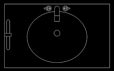
This week's Block is a Vanity with stretchable properties and that keeps the washbasin always centered. You can download the block clicking on the image below.

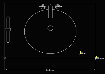
The block is pretty simple, it ahs only one parameter, the distance from one edge to the other, and two actions. The first action is a Stretch action to stretch the contours of the vanity. The second action is a move action to move the washbasin. I have linked both actions to the same parameter for simplicity and to show you how to keep an object centered when modifying a dynamic block. See the Block editor snapshot of the block.

We want the washbasin to stay centered when we stretch the block. This, if you think about it, means that for every unit we stretch the block, we want the washbasin to move 0.5 units.
To do this we need to set a distance multiplier for the move action. We can do that two ways. First one, when you create the action, at some point in the command line you will see this.


If you press M, you will be able to set the 0.5 as distance multiplier. The other option you have, in case you forgot to set this when you created the action, is to select the move action, and go to the properties tab. There, under overrides, you can set the distance multiplier.


What is the other option you see near multiplier? Offset. I will talk about it on next week's Weekly Block.

Show me more...