Need some ACA like tools when using Rhino? This might be the Plugin you are looking for.
Català - Castellano - Deutsch
Rhino is a great modeling software, but you will agree with me that when it comes to simple tasks like creating Walls, windows, Stairs, etc. it is not as efficient as AutoCAD Architecture or SketchUp (specially if you have the 1001bit tools Plugin).
Well that might change if you add to your set of Plugins the VisualArq set of Architectural Tools. This set of tools aims to improve the work speed for Architects, Interior Designers, Etc by adding a set of Parametric Architectural Objects and Documentation Tools.
I haven't had the chance to check it since I only have access to Rhino at work, but from the Gallery on the VisualArq website, the Plugin looks promising.
You will need Rhino's Service Release 5 to be able to use this plugin.
Show me more...
SketchUp Plugins: Loft
The Loft operation is very common in 3D softwares. Now SketchUp has a Plugin to do it too.
Català - Castellano - Deutsch
Chris Fullmer has programmed a Ruby Script to be able to do the common Loft Operation (creating a surface from too Curves). It is not yet a final release of the Plugin and it is not 100% precise, but it does the trick and it is very useful and easy to use.
For those who don't know what a Loft operation is, check this couple of images and see how the surfaces on the right were created from the profiles on the left.
Chris has published a video at SCF where you can see the Plugin beeing used. The Link also works to download the Plugin (you need to be registered).
Show me more...
AutoCAD: Find those Commands You can't Remember
Does it happen to you that you remember a command but not exactly and thus can't tye it properly? AutoCAD will help you with your lack of memory.
Català - Castellano - Deutsch
The list of commands we use in AutoCAD is often longer than we can remember. Nevertheless it is more possible that we remember how a command begins but not the rest of it. We'll, AutoCAD can help you find the end of that missing command in your memory.
If you type the first couple or 3 letters of a command, and then press TAB, AutoCAD will cycle through all the commands that begin with those letters. Keep pressing TAB till you find the command you had forgotten.
It is actually a good way to discover new commands too. By looking a forgotten one you might stumble upon a very useful command you didn't even know that it existed.
Show me more...
Labels:
AutoCAD
SketchUp Books: The Missing Manual
Another Manual to learn SketchUp.
Català - Castellano - Deutsch
If you are looking for a cheap Book to learn SketchUp this might be the one you are looking for. Priced at only $24 dollars, it seems a good choice for those starting with SketchUp who prefer to work with a Manual near the computer.
The Missing Manual offers a good insight on SU's interface, it gives some tips on what the program is best for and has a detailed Index of Menu Entries for reference.
Remember that there is plenty of information about the Program for free on the internet, but if you prefer to learn with a manual to back you up, maybe you want to give this a try.
If you want to check other Books about SketchUp, you can go to the SketchUp section of the CAD Addict Bookshelf.
Show me more...
AutoCAD: Control How You Mirror Texts
Do you want to Mirror Text but AutoCAD keeps it the same way? There is a system variable for that.
Català - Castellano - Deutsch
The System Variable MIRRTEXT controls how texts are mirrored. The default Value 0, mirrors the location of the texts, but it does not actually mirrors their orientation. If you set the value of MIRRTEXT to 1, then you will be able to Mirror the Text or Mtext as if it was any other object, Block, etc. Chek the image below. First is a text mirrored with the MIRRTEXT system variable set to 0, the second one has the variable set to 1.
Show me more...
Labels:
AutoCAD,
System Variables
AutoCAD Architecture: Editing AEC Polygons
AEC Polygons can be very quickly edited using grips. It's a zillion times faster than editing polylines.
Català - Castellano - Deutsch
Somemonths back I wrote a post about Working with AEC Polygons in AutoCAD Architecture.
I thought I would add a video to that post, but since it is old and I rather have all of you subscribers seeing the video I decided to create a new post and link both of them.
So here is the video, it basically shows how you can edit the AEC Polygons by simply clicking on the grips and pressing CTRL to toggle between different editing modes.
Other editing tools, the AEC Modify Tools will be described in a post soon.
Show me more...
Labels:
AutoCAD Arch,
Videos
AutoCAD Weekly Block #08: Cobblestone Pattern
Download this block and learn about the SUPERHATCH command
Català - Castellano - Deutsch
This week's Block is the first that is not a dynamic one. The reason for that is that I remembered I had not talked in here about the SUPERHATCH command. As you will see, the SUPERHATCH command allows you to hatch an area with any custom made hatch.
Why is it in the weekly block section? Well the way SUPERHATCH works involves Blocks much more than it involves hatches (it actually does not involve hatch patterns at all.
The block for download is a cobblestone pattern that my company uses in some of the projects (not everyone gets to work on Zaha's futuristic shapes...lol). You can Download it here. See the snapshot of the block below.
We use this block to hatch certain areas, and the way to do it quick and efficiently is using the SUPERHATCH Express Tool. When you call the SUPERHATCH command, you will see the following menu.
Here you will select Block as an option and use the downloaded "CAD-Addict.com cobblestone" Block. After doing this, simply follow the prompts, basically, you simply need to pick the initial position, rotation and scale, and then pick an internal point of the area you want to Superhatch.
The result will be a set of blocks clipped to fit the boundary selected. See below.
Remember that when selecting "internal point" if the drawing is heavy the computer might crash, so I would recommend you to switch off any unnecessary layers before attempting this operation.
This command has more options that have not been explored in this post, but I think you can get an idea of how powerful this is.
Show me more...
Labels:
AutoCAD,
Blocks,
Downloads,
Hatch Patterns
SketchUp Plugins: Extrude Edges using Edges
A Plugin to extrude a curved edge along a curved path.
Català - Castellano - Deutsch
Ruby programmer TIG has recently released a new awesome Plugin for Sketchup called extrudeEdgesByEdges.rb. With this Plugin you can extrude an edge along another one.
You can go to the original post at sketchucation.com to Download the plugin (you need to be registered). Before you do, see a quick snapshot of what this Ruby code does.
Chek here how to Install SketchUp Plugins.
Show me more...
AutoCAD: LISP Routine for Converting Splines to Polylines
A LISP Routine to Convert some SPlines to Polylines. It has some bugs though.
Català - Castellano - Deutsch
I was recently looking for a way to convert Splines to Polyines and found a LISP routine via Cadalyst. The routine works fine for Splines that we create from scratch. Unfortunately it doesn't work properly for Splines that have been generated when we offset an ellipse. In that case, the resulting polyline does not correspond to the spline we selected. For any other spline, it seems to work properly. You can download it at the cadalyst website.
As I previously explained, remember that you have the option to create ellipses as such or to do it creating an ellipse looking polyline through the PELLIPSE system variable.
Update: Kerry pointed out that there is a much easier way to convert Splines into Polylines. It is as simple as using the FLATTEN command for the spline you want to Convert. Thanks Kerry for the feedback.
Show me more...
AutoCAD Weekly Block #07: Dynamic Escalator - Side Elevation
Download this block and learn about setting angles for Stretch Actions
Català - Castellano - Deutsch
I am a bit behind on my weekly blocks but the truth is that the past weeks are being kind of crazy. Anyways, to catch up with this here comes issue #07 of the AutoCAD Weekly Blocks. This week I am sharing with you a dynamic block for an escalator that I created at work. The idea behind the block is that with a single escalator block we could cover any floor to floor height. First let's see a pic of the block so you know if you have interest reading further.
The original linework is a simplified version of a block obtained directly from Schindler, so the dimensions should be accurate for that manufacturer and very close for any other.
To turn the block into a dynamic one that stretches to fit to any floor to floor height we only need one Linear Parameter and a Stretch Action. Although the stretching we want to do has to be along the 30 degree angle defined by the escalator, we don't want to set the linear parameter in that direction. Let me explain you why. If we do so, the distance of the linear parameter will be the longitudinal distance of the escalator, that way, we would need some guides to know till what point we want to stretch it. What I want is to define the linear parameter to define the floor to floor distance but have the escalator stretch along the 30 degree slope. As complicated as it sounds in writing, it is very simple when it comes to defining the parameter and action. See the image below.
I defined a linear parameter to describe the floor to floor height (Distance in the image) and a Stretch Action. You can see the Stretch Polygon associated to the Action in a dotted line when you select the action. If we simply defined the parameter and action this way, the block would stretch vertically following the direction of the Linear parameter (distance). Instead we want it to stretch along the escalator direction (the 30 degree slope). The simple extra step we need to do for this is to select the Stretch action, go to properties and set the right angle.
In this case, the right angle is 300 (instead of 30) since the Angle count starts with the Distance parameter, not with the XY axis.
As you can see it is a very simple procedure and now you can use a single block while your boss decides what floor to floor height he really wants. You can select the grip of the block to extend it or, easier, go to properties and set the distance to the floor to floor height you need. You can Download the Block Here.
Show me more...
AutoCAD: Placing Objects Along a Curved Path
Need to place obects evenly along a curved path? Two Commands will do that for you.
Català - Castellano - Deutsch
Placing objects evenly spaced and properly aligned along a curved path is something I have to do pretty often. Either if it is because I need to place trees along a curved sidewalk or because I want to have a floor pattern that smoothly adapts to a curved shape. The commands DIVIDE, and specially MEASURE are ideal for this task.
These two commands work in a very similar way, DIVIDE let us place objects evenly along a path, dividing the path in the number of segments that we assign, while MEASURE will allow us to choose the distance between elements. To use these commands to place objects, we need to make a block of the objects we want to place along the path. Name the block with an short and easy to remember name because you will have to type it manually.
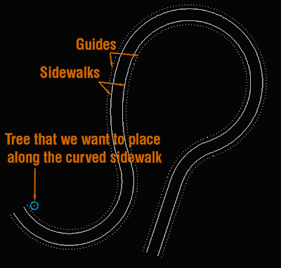
If for instance, we want to place trees every 10 meters along a sidewalk of a road, we need the block of the tree we want to place (for this example let's imagine a block called tree01), we need the entire curved sidewalk to be a polyline, and to make it easier we need a guide paralel to that sidewalk curb that will be along which we will place the trees. See the image below that describes the needed elements.
Once we have this, we simply need to run the command MEASURE (you can simply type ME), select one of the guides when prompted "select object to measure". Then we will enter "B" and ENTER to be able to select the block. On "enter the name of a block to insert" we type "tree01" or whatever name of the block you want to place. On "align block to object" we will generally say YES. The last thing to do is to "specify length of segment" which is the distance we want the Blocks to be apart from each other. If we repeat the process for both sidewalks, the result will be something like this.
We will use MEASURE most of the times to do this sort of block placements because it allows us to pick the distance between blocks. If we knew the number of blocks we would like to place instead of the distance between them then we would use the same procedure with the DIVIDE command instead of MEASURE.
Show me more...
CAD Addict emails are Slow in MS Outlook
I am working to find out a solution
Català - Castellano - Deutsch
Kerry and Cristophe have recently pointed out an issue with the email subscription to CAD Addict. Aparently reading the emails in Outlook has become slow since May 20th. I´ve been doing some research and aparently that is a common issue to other blogs subscriptions (see this post). I am looking for solutions althought it seems to be a bug that someone form google should fix. Please bear with me till this get solved.
ANd Again thanks for reading.
Show me more...
Labels:
General
Subscribe to:
Posts (Atom)