Català - Castellano - Deutsch
When doing detailed sections and other similar drawings, we tend to not draw the entire length of a facade. Rather, we detail certain parts and represent them in a sequence. To separate those different parts we use the break line symbol. This symbols also used on floor plans to represent the point where the stair intersects with the cut plane of the floor plan (at school they always told us to consider 1.5m as the cutting plane for floor plans)
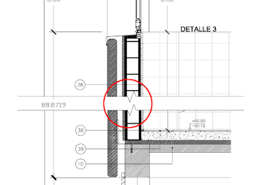
AutoCAD has an express tool to draw the break line symbol, no big secret. Simply enter BREAKLINE or go to Express --> Draw --> Break-Line Symbol. You will enter the 2 points you want the break-line symbol to reach, and the third point you pick is where the jogged line will appear. See how in the detail below, 2 break line symbols have been used to separate the different parts of the detail.
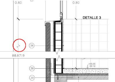
If there is an element that we want to dimension that gets cut by this break line, we might want to represent the dimension symbol with a jogged line too, so whoever reads the drawing understands that the dimension shown is the real dimension not considering that we have cut part of the drawing for representation purposes. To do this, we need to use the command DIMJOGLINE, that will allow us to add the jog line to an existing dimension. The result being something like this.
Show me more...


