SketchUp Plugins: Create Custom Windows / Curtain Walls

Easily create Windows with a Plugin that works as good as windowizer but that will do any window shape or custom design.
Català - Castellano - Deutsch
I wrote not so long ago about Rick Wilson´s Windowizer Plugin to create Windows from a face. Windowizer is great, but it only creates windows based on a regular grid (number of rows - number of columns).
TIG's Latticeizer (Laticeizer.rb) does what Windowizer 3.0 can't. It creates a window with it's mullions and glass parts from a series of faces, cleaning up the intersections very neatly. See how from this set of faces (all faces have to be coplanar) i easily created a custom window.


All faces need to be coplanar and need to be Grouped. The dialog Box will let yo choose the settings, sizes, colors, etc. Pretty Cool. Thanks TIG!!


Download the Plugin Here.

Show me more...

AutoCAD Express Tools: Replace Blocks

Replace all the instances of a Block for a different one with this express tools.
Català - Castellano - Deutsch
I use quite often simple Blocks as placeholders for parts of the drawing that might change or get more detailed in the future. This might apply to windows, doors, toilets, staircases,etc. We might want to put a placeholder to have a rough idea of the space needed for those objects, and later on we might want to replace that placeholder for the final and more detailed block. How do we do that in a simple and fast way?
We use the BLOCKREPLACE express tool. With this command, we can easily pick the block we want to replace and the Block that will replace it. When we enter the command, we will get the following dialog box, where we enter the name of the block to be replaced. If we don't remember the name, we can simply press the pick button and select the block on the screen.


After selection the block to replace, the same dialog will ask us for the block we want to use as a replacement. For this command to be effective, we must have two blocks that have their 0,0,0 coordinate (their insertion point) at the same location, and not be rotated differently. Otherwise, the new blocks will not show in the proper location or with the proper rotation.


Show me more...

SketchUp: Site Design - Randomizing Vegetation

How do you randomize the scale and rotation of a series of objects? Wiht one of Chris Fullmer's Plugins!
Català - Castellano - Deutsch
On my recent post about site design, we saw how to easily place trees on site using the Drop plugin.
Once those trees where placed I found myself wanting them to be a bit more random. I didn't like the fact that all of them where the same size. The intention was to ebable to Select them all and turn them into randomly scaled-rotated copies. So I asked at the Sketchucation Forums, and I got the answer to my wishes.
Chris Fullmer's SCALE ROTATE MULTIPLE (clf_scale_rotate_multiple.rb) does exactly that. You simply select a set ob objects, and run the plugin through Plugins --> Chris Fullmer Tools --> Scale and Rotate Multiple --> Scale and Rotate All Randomly. On the dialog box you set the paramaters of maxim and minimum scale and maximum and minimum rotation and that's it. See how the All equal trees on the first image become randomly scaled on the second one.

IN this case the rotation doesn't matter because of the simplicity of the tree component, but if I ever replace it with a more complex/realistic tree, the instances will be also randomly rotated.
To download the Plugin and to see a quick explanation video, go to the Sketchucation original thread (need to be registered to download)


Show me more...

AutoCAD: Breakline and Dimjogline

Draw the breakline symbol and dimension elements that contain this symbol properly
Català - Castellano - Deutsch
When doing detailed sections and other similar drawings, we tend to not draw the entire length of a facade. Rather, we detail certain parts and represent them in a sequence. To separate those different parts we use the break line symbol. This symbols also used on floor plans to represent the point where the stair intersects with the cut plane of the floor plan (at school they always told us to consider 1.5m as the cutting plane for floor plans)
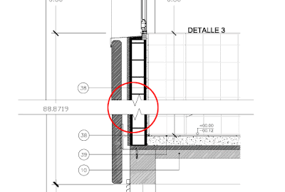
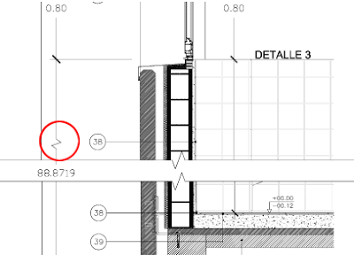
AutoCAD has an express tool to draw the break line symbol, no big secret. Simply enter BREAKLINE or go to Express --> Draw --> Break-Line Symbol. You will enter the 2 points you want the break-line symbol to reach, and the third point you pick is where the jogged line will appear. See how in the detail below, 2 break line symbols have been used to separate the different parts of the detail.


If there is an element that we want to dimension that gets cut by this break line, we might want to represent the dimension symbol with a jogged line too, so whoever reads the drawing understands that the dimension shown is the real dimension not considering that we have cut part of the drawing for representation purposes. To do this, we need to use the command DIMJOGLINE, that will allow us to add the jog line to an existing dimension. The result being something like this.


Show me more...

SketchUp. Adding Text to Dimensions and Keeping them Dynamic

Add descriptive text to your dimensions without breaking the capacity of these to get updated dynamically
Català - Castellano - Deutsch
From the official Google SketchUp Blog we get this tip on how to add text to dimensions and keep them dynamic. Once we have placed a dimension, this will update if the objects link to it move. When we add the text, the dimension will not update anymore unless we do this.


The trick is simple, once you added the text, replace the dimension value for <>.This will show your text and the dynamic dimension near it. If you want to have a line break (windows only) add this \n where you want the line break to happen.


Show me more...

SketchUp Plugins: Site Modeling - Place Trees

Easily transfer your trees from your 2D drawing to the right position (height) on your site model.
Català - Castellano - Deutsch
I've been working on a complex site model and needed to add several hundred trees on it. I found a Plugin that once you have the trees drawn in CAD 2D makes it a two click process to put the trees on your site.
The plugin drop.rb drops objects till they hit some base plane. This is very useful to place our trees on the site. What we do, is we simply import the file were all the trees are in 2D.


Once we have imported the CAD file with the trees into SketchUp, we move the trees higher than our site, select them all and with a right click we select "drop at intersection". The trees will drop till they "hit" the site, each of them being placed at the right height.


Once they are dropped, we can edit one of them to turn them into a 3D tree. Since they were blocks imported from AutoCAD they act like components, so all the trees will be updated.


See this last view of the street wit all 3D trees placed at the right height. All with a two click process.


You can download the plugin here.


Show me more...
SketchUp: Hide Unwanted Edges

Hide those edges you don't want to see in an easy and quick way.
Català - Castellano - Deutsch
Almost a year ago, I wrote a post on How to hide all the edges of an object. Although what it's there is still valid if that is what you need, there is a much better way to do this.
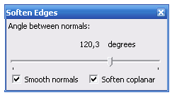
You simply need to select the geometry you want to hide the edges of, and go to Window --> Soften Edges. This will bring the smooth soften edges dialog box to the screen, where you can play with the options of how to soften (hide) those edges.


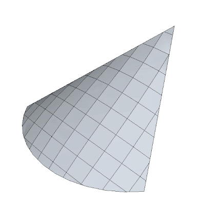
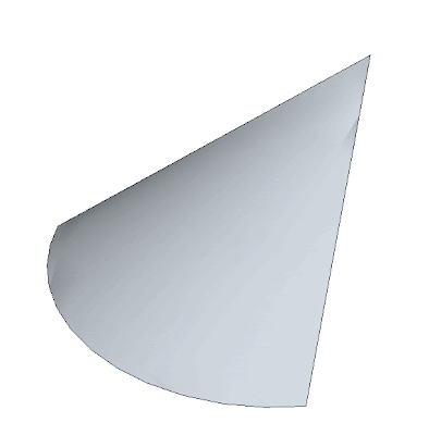
As a quick example see how this surface created with Soap Skin Bubble, was soften to show how I wanted.


What you need to understand though, is that you are not just hiding the edges, you are joining the two faces too. The resulting surface will be one.

Show me more...
Rhino Plugins: Export to SketchUp

Export files from Rhino to SketchUp skipping any oder transition format
Català - Castellano - Deutsch
When exporting files from Program to Program the best way to go is to to the export directly between this two formats. Generic formats like 3Ds work, but tend to make the process tedious, and generally the resulting file needs some clean-up.
For the transition between Rhino and SketchUp, there is a Plugin to export files from the former to the later directly.
The plugin can be downloaded here. More information about it, on the McNeel website.
I've been out on vacation for a couple of weeks. I'll try to catch up with lots of posts I have on a list during the next weeks.


Show me more...

Select Similar Objects / Blocks / Components

Learn how to select all the instances of a component
Català - Castellano - Deutsch
I post often how to find ways to mimic behavior of different programs. We get used to certain tricks that make us work fast and then we miss those things when using a different software.
This is the case of the AutoCAD Architecture function "Select Similar". What this does is to select all instances of an object with the same properties. For instance, if we select a wall, right click and choose "select similar" in the context menu, all the walls of the same style on the objects layer will be selected. The same happens with any object sharing properties and layer with the selected objects.


So how do we do this in SketchUp? There is actually not one method that does all this, but there are several ways to achieve a similar result. If what we want is to select all the instances of a component (the equivalent to Blocks in SketchUp) we need to open the component browser (Window --> Components), then right click the thumbnail of the component we want to select and choose Select Instances (we already went through this on a previous post about How to Replace all instances of a Component).
If what we want is to select all the objects on a Layer, we can simply select one object that lays on that layer, right click it and go to Select --> All on same Layer.

These tricks on SketchUp don't do exaclty the same as the very useful "select similar" command of AutoCAD Architecture and the other AEC versions of AutoCAD, but they are close enough.

Show me more...

SketchUp Plugins: How to Draw a Helix or a Spiral

Easiy draw helixes or spiral curves with this simple plugin.
Català - Castellano - Deutsch
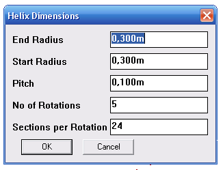
DRAW HELIX (drawhelix13.rb) by Peter Brown allows us to draw helix and spiral curves (flat helix). It is very easy to use and quick. It is accessible via Draw --> Helix (I've modified slightly the original code that was pointing to Draw --> DrawHelix13). It shows a dilog box like the following one, where you can set the different options.


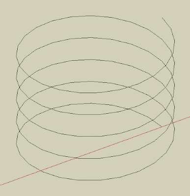
Pitch is the Height of one Helix Rotation. That way, if we set the pitch to 1m and number of rotations to 5, the total heght of the helix will be 5m. The number of segments per rotations will define how many lne segments will form each rotation. This is the result obtained with the default values shown on the image above.


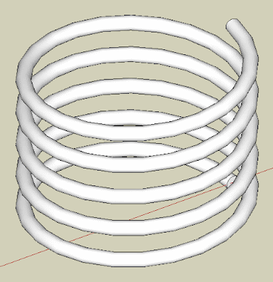
By using a plugin like TUBE ALONG PATH, we are able to turn the helix line generated to a rederable helix.


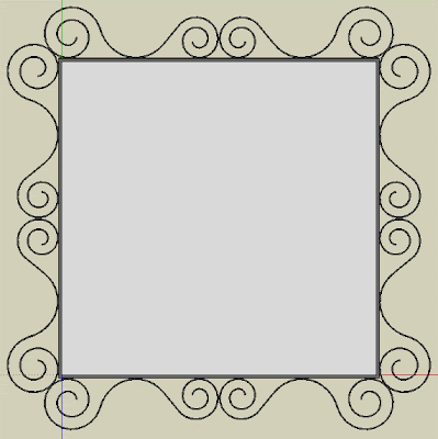
If we want to draw spirals (a flat helix of changing radius) we simply need to set the Pitch to 0. See how I modeled my ugly living room mirror ;).


Chek here how to Install SketchUp Plugins.


Show me more...

Maxwell Render: New 2.0 Version Coming Soon

Check out the new features of the upcoming version 2.0 of Maxwell Render.
Català - Castellano - Deutsch
Next Limit is announcing on their website the new features of the soon to be released Maxwell render Version 2. The website has plenty of examples of the improved features comparing them to the latest released version v1.7.
So far, for what I've seen on the website, the speed improvement (one of the weak points of Maxwell has always been speed) is amazing, and the behavior of light sources has also been tremendously improved.
I can't wait for the release of this new version and find out about all the new features.


Show me more...

AutoCAD: Use Curved Frames to Clip your References

Clip your Blocks or XREFs using curved polylines, circles, etc
Català - Castellano - Deutsch
A common problem found when using the XCLIP command is that it doesn't clip properly if the polyline we use has curved segments. The same way we can't use circles to clip Blocks or XREFs. If you try to clip a block using a polyline that contains curved segments you will see that along the curved segment the clipping is not done properly. See the following image. The block was clipped using the yellow polyline. The result is not satisfactory at all.


The first image shows the original block, the second one is the block clipped with the XCLIP command. As you see we need a work around this result. The work around is to use an Express Tool Command.

CLIPIT is an express tool command that will allow us to do what we wanted to do. CLIPIT will ask us to select the new clipping frame, that can actually be a POLYLINE, CIRCLE, ARC, ELLIPSE, or TEXT object. It works the opposite as the XCLIP command. With CLIPIT you first select the frame and then the Block, Image, Wipeout or XREF you want to clip. See the following image with the result.


What CLIPIT does, is turn the curved clipping frame into a set of segments. If you switch on the XCLIPFRAME and select the block, you will see that the frame is actually made of straight lines. See it below.


The only bad part of this express tool, is that so far (till version 2009) it doesn't allow inverted clips. We talked about how useful inverted XCLIPS can be on a previous post. Hopefully in future versions of AutoCAD this will be solved.

Show me more...