Google Building Maker: Model for Google Earth without SketchUp

Model Buildings for google earth using your web browser.
Català - Castellano - Deutsch
Google has a new tool to crowdsource the 3D modelling of the earth. It is called Google building Maker, and it allows users to model Buildings from pictures that Google itself provides. See this video to understand the process.


It seems a pretty brilliant idea on the path of making the modeling of buildings available to everyone. Of course Google will get cash out of your free labour, but still, it is worth a try just for fun. Try Building Maker Here.


Show me more...

From CAD to BIM: Part I - History of CAD

A brief history of CAD to understand the path that led to BIM
Català - Castellano - Deutsch
I mentioned on a previous post my intention to go into BIM and IPD. Unfortunately for now, I have not the luck to be working on a daily basis with either, so my initial approach here will be more theoretical. I am trying to build the basis of what my Master Thesis is going to be, so forgive me if sometimes things sound a bit basic or repetitive.

BIM, as I see it, is still Computer Aided Design, but it allows you to add an “n” number of dimensions (like costs, scheduling, etc), and strongly modifies the work process to design, build and maintain a building. But since it is in my point of view an evolution of CAD, I think it is important to start with brief history of CAD.

In 1957, Dr. Patrick J. Hanratty had developed the first commercial CAM (Computer Aided Machining) program. It was a numerical control (NC) machining software developed in Pronto , the first NC commercial programming language. Hanratty is regarded as the father of CAD / CAM since these two branches became slowly one.

The first CAD software with a graphical interface was Sketchpad, developed in 1963 by Ivan Sutherland. Sketchpad was a Program in which the user could graphically interact with the program through a screen, a light pen used to draft, and a set of buttons that allowed the user to enter parameters and constraints. Although it never became commercially available, the ideas on Sutherland´s PhD dissertation became highly influential for future generation CAD developments.


First-generation CAD software systems were 2D drafting applications developed by a manufacturer's internal IT group and primarily intended to automate repetitive drafting tasks. During the 1960s, Hanratty himself developed DAC, a CAD system, while working for General Motors Research. Other companies like Ford (PDGS - 1967), McDonnell-Douglas (CADD - 1966), and many others followed soon after that.

During the 1970s the transformation from 2D to 3D began. The French Aerospace Company, Avions Marcel Dassault, developed CATIA, after purchasing a source code license from Lockheed Martin. CATIA is still nowadays leading software in the Aerospace, Automotive and Shipbuilding Industries. One of the most important research dissertations of the decade was K. Vesprille's (at Syracuse University) 1975 PhD dissertation "Computer-Aided Design Applications of the B-Spline Approximation Form" on Complex 3D Modeling. It is from the end of this decade that one of the first books marketing CAD for architects appeared. “Computer Aided Architectural Design” by William J. Mitchell from 1977 is a hint that CAD was already being marketed to architects. The widespread adoption by architects would take still years.


During the 1980s the CATIA, Pro/Engineer, Unigraphics and I-DEA became the leading CAD software packages. All of them powerful 3D modeling software systems with their core business on the industrial production (for this reason sometimes referred as CAE systems rather than CAD) and their main hardware platform being UNIX. On the 2D and PC Platform Autodesk, with AutoCAD, was gaining market share.

It was on the 1990s, that the PC explosion happened and with it the raise of a new player. Autodesk had been focusing on the PC platform since its AutoCAD version 1 released in 1982. The licensing of the ACIS 3D Kernel, allowed Autodesk to release in 1993 AutoCAD Release 13. For the first time AutoCAD had 3D Solid Modeling Functions. AutoCAD became widely spread, but other packages like Bentley’s Microstation, soon became strong competitors on the mid-price market. The widespread adoption of CAD by architectural offices was happening slowly and soon would burst into being the dominant trend. We will see more on that on the next post on this series

Sources: CADAZZ, American Machinist

Show me more...

Book of the Month: LEED Visual

Study for the LEED GA exam from this great book.
Català - Castellano - Deutsch
If you are studying or thinking to study for the LEED GA Exam, you need to get this book in your hands. The amount of information to memorize is not few. This book turns all that information into useful and easy to remember and understand diagrams. LEED Visual is a new publication that aims to help everyone who wants to study for the LEED GA exam. The book is available via Amazon (click on the picture below)or directly on the LEED VISUAL website.


Some of the customer reviews say "it's the best book available currently for LEED GA. By converting the pages and pages of written information from the official USGBC study guide into easy to remember visual diagrams, this concise book is a fantastic guide for the exam. Visually Appealing, Easy to carry, Compact and Graphically rich, this is a MUST BUY for anyone planning to give the Leed GA Exam".

Find more information and a preview of the book at www.leedvisual.com


Show me more...

Photoshop: Shortcut to select all the contents of a layer

Select all layer contents wit a single click
Català - Castellano - Deutsch
When working with Photoshop sometimes we might want to get a selection of the entire content of a layer. This is useful for man reasons. An easy way to do this is to go to the layers tab and click on the thumbnail of the layer with the left mouse button while holding CTRL (I guess command key in MAC??)
If you point at the layer thumbnail with your cursor and press CTRL, you will see how the cursor will change from a pointing hand to a pointing hand with a marquee on top. This means that when you click there instead of selecting the layer as active, it will use the contents of that layer to create a selection.
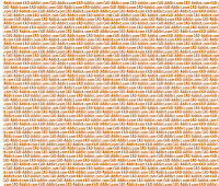
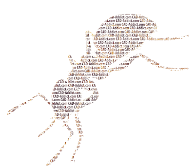
This is very useful to create selections based on the shapes of layers such as texts. See this example that I created using this method. From the following two images...


...i used the one on the right with the multiple CAD-Addict.com texts to create the selection using the explained method. Then, I used the slection to erase parts of the layer on the left. The reslult is as follows


This is a very useful trick to speed up you workflow in pshop.


Show me more...

AutoCAD: Load LISP and Applications Manually or Automatically

Hot to load LSIP routines and other applications
Català - Castellano - Deutsch
I wrote recently some posts about using LISP routines to speed up certain tasks. I forgot to mention, how to load these Files. The manual way is to use the command APPLOAD. This will call the Load Application Dialog Box where you can browse for the saved LISP.


Alternatively, if it is a LISP that you use regularly, simply drag and drop it into the icon saying Startup Suite in the APPLOAD dialog box. This will make the LISP or application load automatically at start of the AutoCAD session.


Show me more...

Excel: Turn numbers exported from ACAD into European Format

There is a quick way to turn numbers in Excel into European format and to remove apostrophes.
Català - Castellano - Deutsch
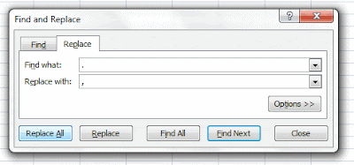
European Number Format, uses a coma as a decimal separator instead the period of the English format. When exporting data from AutoCAD to Excel using the DATAEXTRACTION command, the numbers exported are in English format, so to transform them to the European Format we need to replace the points for comas. This can very done very easy by using the find and replace function in Excel. Type CTRL + F or click the Replace button on the Editing area of the Home Tab (Excel 2007). Find Points and replace them by comas, and select Replace All.


There is an extra step needed if we want to be able to use the data from AutoCAD in Excel as numbers. All the Cells exported from CAD start with an apostrophe ('). See below.


This makes the numbers not usable as such. Luckily there is a trick to batch remove this sign. If you have a column with numbers, insert a new column to its right. On the cell next to the first number in the row enter the follwing fórmula.


Where D2 is the Cell with the numbers with the apostrophe you need to eliminate. Then copy the cell next to all numbers you want to transform. You will see now the result of the formula as the number you want to use. Something like this:


The left cell is the one still containing the apostrophes, and that is why the numbers are aligned to the left. The one on the right is the result of the formula we have applied.

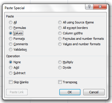
A final step I would recommend is to copy all these new cells and paste them in a new column using Paste Special. Paste Special can be accessed after copying some cells by right clicking on a cell. Then On the Paste Special Window Select "Values".


That's it, now you can delete the other columns (the one with the apostrophes and the one with the formulas, and you have just the new column with plain numbers. The explanations is long, but the process takes lest than a minute.


Show me more...

AutoCAD: AutoLISP to Generate Multiple Hatch Boundaries

Do you need to re-generate the boundaries of multiple hatch patterns? An AutoLISP routine will do it.
Català - Castellano - Deutsch
I had to work on some files converted from ArchiCAD to AutoCAD and needed to use the AEC Space entities to get the areas. Unfortunately, plain AutoCAD doesn't read the are of this objects, and by exploding them, it generated Hatch Patters that would not show their area on the properties palette.

The solution for a single AEC_SPACE, was simple, explode it, regenerate the boundary of the Hatch Pattern, and select the resulting Polyline to see the area (or to extract the area to an excel file as explained on a previous post). The problem came becuase there were a lot of this AEC_SPACE objects,and AutoCAD does not allow to regenerate boundaries of multiple Hatch Patterns at the same time.

The solution was found via DigitalCAD, in the form of a LISP routine called HATCHB.LSP. This routine when used, allows you to select as many Hatch Patterns as you want and obtain their boundaries in the form of polylines. The polylines will be generated on the current layer, and properties.

Some thoughts: This real life situation is a clear case that shows how format incompatibilities makes us waste a lot of time. In this case the lead architect works in ArchiCAD, but we as Contruction Managers have only AutoCAD, so everytime we get files from them there is a lot of information in those files that is wasted, because we can not read it properly, so we have to waste hours on retracing polylines to be able to double check the information we have received...


Show me more...

About me - 2010 resolution

The BIM revolution is happening right now, I wanna be an active part of it.
Català - Castellano - Deutsch
I have never introduced myself properly in my own blog, kind of rude, but as some of you already know it all started as a record keeper of little things I was learning. The snowball became bigger and bigger, and then i forgot to be polite. Since this article needs a bit of my own background I am going to start with that.

My name is Martí Broquetas, I am an Architect from Barcelona. For those who don't know it I am currently studying a Master in International Building Project Management and working at the Construction Management Team at a big Project Management Company in Stuttgart, in Germany.

Before moving to Germany in September '09, I worked for the previous 3 years in Baltimore, MD in a mid sized (nearly 100 employees) Architecture and Design Firm, I worked as a Project Designer on big projects all over the world. After learning the insights of a big architectural practice i realized I wanted to get a better insight of the construction industry itself, and for this reason I chose the IBPM Master in Stuttgart.

My workflow has mostly comprised working with CAD Design softwares like AutoCAD, Microstation, SketchUp and Rhino and doing some tweaks with Photoshop and other image editing programs. This is the reason why most of the posts are related to these programs.

I haven't wrote much about BIM here since unfortunately it has not been part of my workflow since I started this blog. But I am intending to change that soon. I am very much decided on writing my Master Thesis on the role of Building Information Modeling (BIM) and Integrated Project Delivery (IPD) to make the Design and Construction Process more efficient (I know, i need a shorter title line). I am not an expert on either, but I intend to become one.

So from now on (it might take a couple of months to really get something interesting enough to be published here) and with the same spirit of sharing knowledge that made CAD-Addict what it is, posts related to this two topics will hopefully appear here as often as possible. The idea is not only to publish posts that explain better ways to work with BIM programs like Revit or ArchiCAD, but also to encourage the discussion about the need for change in the way architects work to make building design a much more efficient practice.

The website is named CAD-Addict, and for a while i thought to maybe start a separate blog for the topic. But I sincerely think it is better to have the discussion here, since pure CAD users can benefit from and contribute to the discussion about BIM and IPD a lot. Plus, I am sure a lot of the readers of this blog are already BIM users. Aren't you?


Show me more...

AutoCAD: Project Butterfly Works as a Free Version Converter

Use the new Autodesk cloud CAD tool as a free translator between AutoCAD versions
Català - Castellano - Deutsch
I discovered recently the so called Project Butterfly (update: now released as AutoCAD WS) from Autodesk. See this previous post for a more general overview to it. It is basically a lite version of AutoCAD that resides entirely on the cloud, meaning you can use it by simply having an up to date web browser.
What i recently realized, is that this "program" can be actually used to convert files from a newer version of AutoCAD to an older one. In case you get some AutoCAD file in the newer 2010 format, but you are not using AutoCAD 2010, you will not be able to open the file. normally you would have to ask whoever sent you the file to "please save it in 2007 / 2004 version". Using Project Butterfly you can skip that request and do the conversion to an older version yourself.
Project butterfly can read files in the new 2010 format. This files then can be downloaded. the trick is that when you click on the download as DWG button on the upper right part of the PB interface, it asks you in which version of AutoCAD you want to download the file. See the image below.


Although this is not the main goal of this application, well, it can be used for that. The limitations are that it saves only in 2004, 2007 or 2010 versions, so if you are working on an older version than that, this won't work, although maybe you should consider Upgrading...
This is the link to the Project Butterfly website, you'll need to register to be abel to use it, but it takes 1 minute.


Show me more...

AutoCAD: PEDIT Command Without Confirmation

A trick to speed up the PEDIT command
Català - Castellano - Deutsch
PEDIT is a command that allows us to edit Polylines. It also allows us to edit lines, arcs and splines, by asking us the question we many hate
"Object selected is not a polyline
Do you want to turn it into one? "
Although this might be useful to remember that the geometry selected is not a polyline, it turns to be an extra click that we would love to skip. We will skip it from now on thanks to Josh from Lazydrafter.
Josh posted recently about the PEDITACCEPT system variable. The variable is by default set to "0", and that is why AutoCAD asks us that annoying question. Well, set it up to "1", and the question is gone. Now it takes no extra step to edit lines, arcs. Spline still ask for the conversion factor, but still you'll be saving couple of clicks. All to work faster!


Show me more...

AutoCAD 2010: New System Variable to Fade XREFs

AutoCAD 2010 has a new system variable to fade XREFs.
Català - Castellano - Deutsch
New versions come sometimes with some nice surprises. One I just discovered by using AutoCAD 2010 at work is the XDWGFADECTL system variable. We had seen long ago on a previous post how to control the fading of locked layers and the objects seen outside the REFEDIT mode. Just as a quick reminder on that since that is a very old post.

LAYLOCKFADECTL directly controls the intensity of the fading of locked layers.
XFADECTL is used to control the fading when we enter the REFEDIT mode (everything that does not belong to the XREF that we enter to edit in place will be faded).

This was what we had available so far. In case we wanted to fade the XREF, my common procedure was to set the fading of the LAYLOCKFADECTL to between 30 and 50% (depending on the screen), be sure that all my XREFs where in one layer, and lock that layer. This would allow me to see my XREFs fades, making very easy to understand what was in the current drawing and what was a reference.
The only problem with this is that sometimes, when we had to move those XREFs, we had to unlock the layer and lock it after finishing the operation. Minor nuisance maybe, but it has disappeared from now on.

XDWGFADECTL is one of the new system variable added to AutoCAD 2010 that allows to control how XREFs are faded. It is useful. It might seem a minor tweek, but when you are using a dwg as an underlay to draw something else, it is really practical to see this dwg faded. And although this could be done before with the locked layers fading, now we have a second way to do it to suit every situation (or almost every)

Remember that there is a list of all the system variables that have been explained at CAD-Addict following this link.

Show me more...

AutoCAD: SaveAs 2004 Script

A script to save your drawings on a previous AutoCAD version.
Català - Castellano - Deutsch
As I promised on a previous post about Running Scripts on Multiple AutoCAD files, here comes the script to save your files as 2004 version. I found the need of this script recently, when a collaborator of mine was working with AutoCAD 2004 (i didn't know that in advance) and I was working with 2010. After finishing the tweaks on some of the files, he asked me "can you convert them to 2004, otherwise I can't read them". Well there were nearly 40 drawings, so I had no intention to save them one by one to 2004 format. I set myself to generate a script to do that for me.
This is the script file SaveAs2004.scr and let me easily explain how it works. Let's analyse it line by line.
FILEDIA 0 - This line turns off the dialog boxes (see this post for more info)
SAVEAS 2004 Y - this part is the proper saving as 2004 version. we call the saveas command, stipulate 2004 (or any other version we want) and then click yes, because the program will ask us if we want to overwrite the existing file. note here that there are 2 spaces between 2004 and Y, this is due to the fact that the first is to enter 2004, and the second is needed, to confirm the file name. (If you want to understand this better, run the different commands manually with the FILEDIA system variable set to 0, and you will be able to see all the steps I am following).
FILEDIA 1 - here I simply wanna make sure that after running the script the settings return to what they were, so i set the FILEDIA SV back to 1.
CLOSE - Closes the file, be sure that there is a space or an enter after close, since it is easy to forget that being the last text in the script file. This is generally not neecessary if you use a batch scripting program such as Autoscript or ScriptPrp, but in case you run the script directly in one file, this will close the file after running it.
That's it, now you have a script to save as 2004 version. Replace 2004 by, R14, 2004, 2007, 2010, Standards, DXF or Template, and you will save in that format.


Show me more...