Very interesting post from the AUGI Blog: The six phases of Revit. Where are you now?
Català - Castellano - Deutsch
Randomly bumped into this post from the AUGI Blog. As you'll see it describes six phases of how users interact with Revit.
I find myself right in Phase 4: "The family editor eats you up and spits you out". LOL, that is how I feel sometimes when creating families (specially window and door families).
Reading the post I thought I'd ask users here at what Phase are you. Just to know what audience I am targeting. So feel free to click on the answer below.
Show me more...
#IPD: Integrated Project Delivery, an Introduction
I might be talking soon oftern about Integrated Project Delivery (IPD) so I thought I'd attach some introductory documents in case you are interested in following up the discussion
Català - Castellano - Deutsch
If you read the Summary of my Master Thesis published here a few months back, you might remember the topic of the Thesis was focused on BIM, but the fact that I ended up chosing that topic was a consequence of a thorough analysis of literature that indicated this was a relevant topic.
Part of the same literature that led me to study BIM in detail also pointed at "a need for better integration of project teams and collaboration between all parties". BIM is being regarded as one of the tools to enable this needed better integration (we could discuss here if BIM is a tool or a process, if you've been here for a while you might know that I see much more as a process than just as a tool, but we can discuss this point later on on another post).
The main improvement potential for better project outcomes though will not come just from implementing BIM, but also from implementing better collaboration among project stakeholders. There are two main lines of thought about this collaboration. One is the one followed by the Lean Construction Institute and their approach to Lean Project Delivery. The other, and the reason of this introductory post is the Integrated Project Delivery (IPD) paradigm.
We are trying at work to adapt part of the IPD approach to the Spanish Market to reach better project outcomes, improve the atmosphere of collaboration and increase client's satisfaction. We are still in the beginning and have no completed project to show resuts yet, but we are doing our best to adapt this approach to the way things can be done right here.
As an Introduction to IPD for those who know nothing about it there is this document from the American Institute of Architects that I think is a very good read to start.
Integrated Project Delivery: A Guide
I'll share here whatever I can of our journey trying to create Integrated Project Teams for Projects in Spain and Catalonia. I already took part in a sort of Integrated Project Team when I worked in Germany, so hope I can bring my little bit to this challenge. Anyone else has worked under IPD agreements? Any thoughts you'd like to share?
Show me more...
Català - Castellano - Deutsch
If you read the Summary of my Master Thesis published here a few months back, you might remember the topic of the Thesis was focused on BIM, but the fact that I ended up chosing that topic was a consequence of a thorough analysis of literature that indicated this was a relevant topic.
Part of the same literature that led me to study BIM in detail also pointed at "a need for better integration of project teams and collaboration between all parties". BIM is being regarded as one of the tools to enable this needed better integration (we could discuss here if BIM is a tool or a process, if you've been here for a while you might know that I see much more as a process than just as a tool, but we can discuss this point later on on another post).
The main improvement potential for better project outcomes though will not come just from implementing BIM, but also from implementing better collaboration among project stakeholders. There are two main lines of thought about this collaboration. One is the one followed by the Lean Construction Institute and their approach to Lean Project Delivery. The other, and the reason of this introductory post is the Integrated Project Delivery (IPD) paradigm.
We are trying at work to adapt part of the IPD approach to the Spanish Market to reach better project outcomes, improve the atmosphere of collaboration and increase client's satisfaction. We are still in the beginning and have no completed project to show resuts yet, but we are doing our best to adapt this approach to the way things can be done right here.
As an Introduction to IPD for those who know nothing about it there is this document from the American Institute of Architects that I think is a very good read to start.
I'll share here whatever I can of our journey trying to create Integrated Project Teams for Projects in Spain and Catalonia. I already took part in a sort of Integrated Project Team when I worked in Germany, so hope I can bring my little bit to this challenge. Anyone else has worked under IPD agreements? Any thoughts you'd like to share?
Show me more...
#Revit 2012: Using the Create Parts feature for Quantity Take-Off
I am a bit disappointed with the new Create parts feature, let me tell you why.
Català - Castellano - Deutsch
I was very excited about the new Create Parts feature for Revit 2012. I thought it would simplify a lot the process of extracting quantities from a Revit model, by allowing to play with the different layers of a wall or floor (as other BIM packages like Allplan allow). yesterday I gave you the link to the video explaining the features.
My disappointment came today, when I realized that whatever you modify using the Create Parts feature, doesn't get reflected in a default Material Take Off Schedule. My first thought was the following:
The key is that you need to create a Material Take-Off specific to list the parts, and you do it like this:
I am starting to realize as I read on this post, that REVIT CAN DO EVERYTUIN. Well not yet, but it is getting there, and this post and my chain OF thoughts should serve as an example of how sometimes we blame the Software (and the SOftware designers) for our own lack of expertise with it.
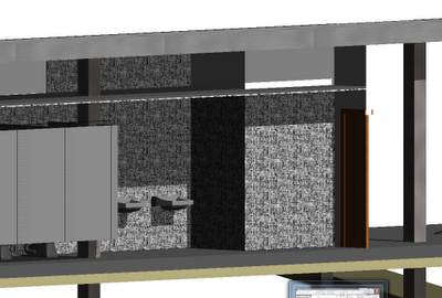
There is just one little BUT I haven't been able to solve. Using Parts combined with Groups doesn't seem to work well. After I created my Bathroom (the one on the first picture) I needed to copy that group all over the buidling since it repeats many times. When I used "Create Similar", the newly create Group, has all the parts reset to default. If you copy the group directly, it does work better, but in my example, some of the parts got reset as well to default.
Need to find out about this point if it is my fault or Revit's fault. So far it seems to be Revit's fault, since I am allowed to modify parts of elements that are inside groups without entering the edit gropu mode, and those changes are not reflected to other instances of the group. A little bug, hopefully it will be solved on Revit 2013.
BTW, I found the solution again via RevitWikiHelp, awesome database of solutions.
Show me more...
Català - Castellano - Deutsch
I was very excited about the new Create Parts feature for Revit 2012. I thought it would simplify a lot the process of extracting quantities from a Revit model, by allowing to play with the different layers of a wall or floor (as other BIM packages like Allplan allow). yesterday I gave you the link to the video explaining the features.
My disappointment came today, when I realized that whatever you modify using the Create Parts feature, doesn't get reflected in a default Material Take Off Schedule. My first thought was the following:
"I tried it, it simply doesn't do anything. So as far as i understand it, the Create Parts feature is just a tool for representation. This to me is the wrong approach to go Autodesk. Revit (and BIM) is not just for representation, if you can't get accurate Quantity Take-Offs and thus accurate estimates from a model, what is the point of BIM?"But then I thought, this can't be it, such a cool feature can't end on a mere representation of parts. So I dug deeper and found that you can use it for Quantity Take-Off.
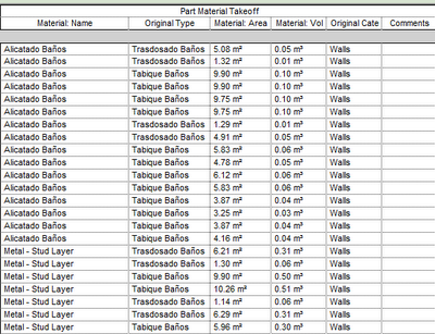
The key is that you need to create a Material Take-Off specific to list the parts, and you do it like this:
- Click View tab > Create panel > Schedule > Schedule/Quantities. Under Category, select “Part”
- Then add the categories you need for your take off, like Material: Name, Material: Area, Material: Volume, etc
I am starting to realize as I read on this post, that REVIT CAN DO EVERYTUIN. Well not yet, but it is getting there, and this post and my chain OF thoughts should serve as an example of how sometimes we blame the Software (and the SOftware designers) for our own lack of expertise with it.
There is just one little BUT I haven't been able to solve. Using Parts combined with Groups doesn't seem to work well. After I created my Bathroom (the one on the first picture) I needed to copy that group all over the buidling since it repeats many times. When I used "Create Similar", the newly create Group, has all the parts reset to default. If you copy the group directly, it does work better, but in my example, some of the parts got reset as well to default.
Need to find out about this point if it is my fault or Revit's fault. So far it seems to be Revit's fault, since I am allowed to modify parts of elements that are inside groups without entering the edit gropu mode, and those changes are not reflected to other instances of the group. A little bug, hopefully it will be solved on Revit 2013.
BTW, I found the solution again via RevitWikiHelp, awesome database of solutions.
Show me more...
Labels:
BIM,
Estimating,
Quantity Take-Off,
Revit
#Revit 2012: Video on the Use of the new "Create Parts"
Revit 2012 has a new feature called create parts to be able to manipulate the parts of complex elements like walls.
Català - Castellano - Deutsch
Just learned about the existence of the Twitter Autodesk account @RevitWikiHelp that provides a lot of links to useful resources on how to better use revit.
I learned about @RevitWikiHelp when they mentioned one of my posts. Now I follow them and I think they will be a great source of new Revit knowledge.
If you followed all the information on the new features of the new 2012 version of Revit, you probably know of the new "Create Parts" feature. this feature is key to work with some elements like exterior walls without the need of using complex Stacked Walls. I'll leave you with the video on this topic, which I think is good enough for you to understand the power of this feature.
Remember you can also follow the Blog using the twitter account @cadaddict where I also post short tips and retweets about Software and Processes for Construction, Architecture and Design
Show me more...
Revit: Organize the View List in the Project Browser
Easy steps to organize the view list in the Project Browser
Català - Castellano - Deutsch
The Project Browser is that window [probably] on the left side of the screen in Revit that you use to access all Plan, Section, 3D, Elevation views etc. I find the default organisation to not be very practical, specially when it comes to organizing the Floor Plan views.
I personally like to have the Floor Plan views to be organised the same way I see them on a Section or Elevation view. That is, the lowest level below, the highest level on top, and organised by elevation. To me this simplifies looking for each plan by mimicking their position on the building. You might want to do this or something different to suit your needs, but I guess this can help you anyway to know how to play with the Browser organisation.
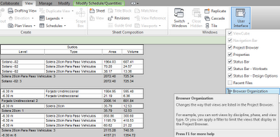
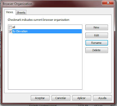
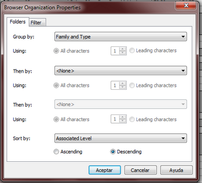
To arrange the views the way you want, you should go to View Tab -> User Interface -> Browser Organisation (see picture above). There you will see that the Organisation you are using is probably the default one, the one that says ALL. This one can not be edited, but you can create a new browser organisation setting. Do that, and name it in a way that will make you easily recall what it is for, so in case you create several of them for different uses, you know what is what.
Then, play with the different settings to arrange the views the way you want. In my case it was pretty simple. Set them to be organised by Family and Type (this way Floor Plan views and Sections will be grouped separately) and then select Sort by -> Associated Level -> Descending.
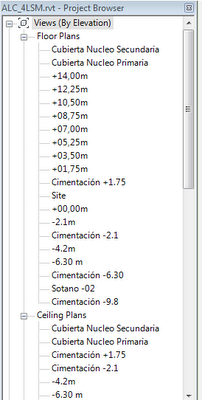
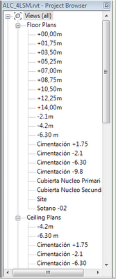
This way I have my views organised by Level, allowing me easier access to them. (see below how the views were organised by default and how they were arranged using this method.
This is probably the most simple way to use this method, but it is key to understand it because for complicated projects with many types of views, you either organize them properly or you will never find the view / drawing you are looking for.
Show me more...
Labels:
Revit
Can all sorts of Brains handle complex BIM models?
Does everyone have the capacity to handle complex 3D models?
Català - Castellano - Deutsch
Not so long ago I was talking to an architect, owner of a small firm, telling him he should seriously consider transitioning to a BIM platform. The only argument I couldn't refute was the one when he said "Everything sounds great to me, but if I wanted to implement BIM tomorrow, I wouldn't find skilled staff to do it" [in Spain]. Point taken, and I do believe it is true right now in Spain. As far as I have seen in the last 6 months, very few companies are using it, and what is most discouraging, students seem to come out of Architecture School with almost no BIM skills. (they ALL know SketchUp and AutoCAD to a relatively decent level, some know Rhino, all "Have heard" about Revit...).
This is a bit discouraging if you think about it, what if we get a huge project that requires us to set up a team of BIMable professionals? Will we find them, will they earn more than management? Questions I am asking myself these days, I guess we will find out soon if things work out.
On the other hand, and with a job market that sucks especially for Architects. Being able to work on a timely manner with complex BIM models might be in the future a very unique selling point on a CV. I have been working on a relatively complex BIM model (around 17000m2, with some 12 different levels, mezzanines, etc) and realized how complex it can be sometimes to navigate the model, to understand and visualize the different spaces inside the building. I am not sure everyone can do that, it requires a set of skills that differ completely with traditional CAD working in 2D dimensions, or even working on 3D for representation (where things can be fudged and faked just so they look good).
Proper BIM models to be used for Estimating, require a capacity to have the building in your brain in 3D to be able to see, find, detect possible errors or missing parts of the building. Shouldn't there be a slab? Isn't the drop ceiling missing here?
I am not very optimistic on the role of the Architect in the industry, and think that if the service delivered by Architects doesn't improve many functions will be taken from architects and delivered by other professionals with better quality.
But here is my bit of hopefulness for Architects. We as architects have learned for many years to think in 3D, to understand spaces, volumes, etc, so we have a slight advantage when it comes to working with complex 3D models. So BIM might be an opportunity for Architects to show they are more then just CAD monkeys drafting lines, and show their peers, bosses, etc that they can be of great help by being able to understand, model, compare, error check, etc complex BIM models.
Show me more...
Labels:
BIM
SketchUp Plugins: Greeble2
Creating a Slum from scratch in 5 minutes thanks to this plugin and a bit of smart thinking
Català - Castellano - Deutsch
My friend Aarti just shared this with me about using the Greeble2 Plugin to create a randomly looking slum for a project she is working on.
She even shared an image of the "quick slum" she created.
I of course felt like trying the plugin to see for myself how it works and produced also a 5 minute slum quite easily thanks to this plugin.
You can download the Plugin here.
Remember to check the List of SketchUp Plugins, you might find something useful.
Show me more...
Català - Castellano - Deutsch
My friend Aarti just shared this with me about using the Greeble2 Plugin to create a randomly looking slum for a project she is working on.
"I desperately needed to show slums in my project and i have been struggling for way to show it in my sketchup model...
image mapping looked shit... and i dont have the time to DRAW a darn slum...
SO i just made a grid in cad, trimmed it to the slum boundaries and imported to sketchup, did intersect, then used the make faces tool, and THEN used GREEBLE (plugin) and VOILA - a randomized height grid shows a beautiful slum made in 5 minutes..."
She even shared an image of the "quick slum" she created.
I of course felt like trying the plugin to see for myself how it works and produced also a 5 minute slum quite easily thanks to this plugin.
You can download the Plugin here.
Remember to check the List of SketchUp Plugins, you might find something useful.
Show me more...
Revit: Using Building Pads Properly - Part II
A second not eon using Revit Building Pads the right way
Català - Castellano - Deutsch
On the previous post I talked about one of the issues I recurrently found when using Building Pads, their incorrect visual representation if you don't create them in a certain way. On this post I'd like to share a few points on how to use them properly to be able to get Cut and Fill counts, to be able to estimate the amount of Cubic Meters of Excavation of a project. On the documentation about Buiding Pads, there is information on how to create them and so on, but I think a few points are missing that are key to be able to use them the right way.
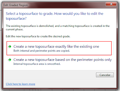
First of all, before creating any Building Pad, set the phase of the Topography to a Phase (I assume Existing would be the right one) and then set the phase of the view to the next one. Then, click on Graded Surface (on the massing & site Tab) select the topography, and on the dialog that appears, select the first option, see below, and simply accept the graded region like that pressing on the green "accept" symbol.
This will create an almost identical Topography to the existing one. If you don't do this first step, you will not get Cut and Fill counts when you create Building Pads. As I understand it, the count works as a comparison between one topography and the other, so without this step there is no topography to compare with.
At this point, you should have two identical surfaces, on on the Existing phase and one on the next one. I would hide the original topography at this point (Select it -> right click -> Hide in View -> Elements) so you know always that you are working with the new one that is the one you should modify.
All set until here. Now it is time to create the Building Pads. Very important point no to miss here. Revit allows you to create Building Pads by simply clicking on the Building Pad Button on the Massing & Site Tab. Don't do that. Be sure that first you select the Topography, then click on the Building Pad Button on the Massing & Site Tab. Otherwise, the Pad will be created, but sometimes (I haven't figured out why and how this happens) the Cut and Fill will not be reported on the Topography Schedule.
Create your Buidling Pad now, I am not going to describe this much because I think it is very simple and the documentation is good enough.
Next point, create a Topography Schedule if you don't have one (ideally your template should include one so you don't have to create one for each project). Then go to it and check what is being reported there. You will see probably three lines on the schedule, but you will not be able to know what is what. An important point to consider is Naming each Topography element differently. You should Name the existing Topo as "Existing" for instance, The copy as "Modified" or something like that and then each Topography created by adding the Building Pad with a different name that will allow you to identify it on the schedule. This is an example of a Schedule with the elements already named properly.
There is a Cut and Fill count on the "Modified" surface which I think comes from the slight difference between the two copies (the existing and modified topos) which might create a slight error on the total count, but my experience is that this amount is always negligible, compared to the total cut and fill counts obtained from the different topos related to the Building Pads.
Last two points to consider: First, creating a Buiding Pad, creates a Topography Element. It's important to understand that these are two separate but interrelated elements, if you delete one, the other will be deleted two (and the Modified topo will recover its previous shape).
Second, if you want to modify the Building Pad, you need to select the Building Pad Element (not the Topography Element) and then click on the "Edit Boundary" button that will appear on the ribbon. Unfortunately (as of Revit 2012) the Edit Boundary button does not appear if you are on a 3D view, so you will have to select the Pad from a Floor Plan view or similar. Since this might not be easy because all the elements that might show on that Floor plan view. I would select the Building Pad on any view where it is easy to select (I always have an Excavation 3D View with just Topos and Building Pads visible) deselect it, go to the Floor plan view and use the Select Previous function.
I think with this post and the previous one you can perfectly work with Topography and Building Pads and get accurate Cut and Fill quantities and the right visual representation. Hope this helps.
Show me more...
Labels:
Quantity Take-Off,
Revit,
Site Design
Revit: Using Building Pads Properly - Part I
There are a few things you need to consider when using Building Pads.
Català - Castellano - Deutsch
I've been using Revit Building Pads a lot recently to show the excavation needed for a project were are working on. The point was not only to show it visually, but also to use it to get the quantities for the excavation and so to be able to get an accurate budget for the works needed to build the underground levels of the building. This post deals with one of two different topics, the two topics are: one about some issues related with visual representation (on this post), the other about some issues related to the true BIM use of building pads, getting accurate quantity take-offs (on the next post).
Visual Issues: I realized that when using sloped building pads sometimes you get this sort of effect.
Getting this sort of "side wall" that shouldn't be there happens if you set the reference level of the Building Pad to be the top level and then slope it to go down to the level below.
If instead of that you place the Building Pad on the lower level and set it to go up to a higher elevation, then you will get the right effect, or to be accurate, a better visual effect. I think Building Pads can be still improved quite a lot.
Show me more...
Labels:
Quantity Take-Off,
Revit,
Site Design
Brief Introduction to the benefits of Lean Construction implementation by Glenn Ballard
A short video with some insight on Lean Construction by Glenn Ballard
Català - Castellano - Deutsch
For those who don't know about Lean Construction (and for those who do) I think this video is a nice way to learn a bit about it from one of the initiators of these way of working that is rapidly spreading all over the world. It is just a short conversation with Glenn Ballard, but it highlights some of the principles behind Lean Construction, specially the need for a change in mentality rather than a simple change in tools and software.
Of course the savings of 15-20% being accomplished by using this methodology should not be forgotten. At the end, some AEC professionals are only driven by cost, and it is logical.
via Lean Construction Spain
Show me more...
Labels:
Lean Construction,
Videos
HOK's Approach to Social Media
Ken Young, Chief Information Officer at HOK explains HOK’s experience using social media.
Català - Castellano - Deutsch
Social media is a hot topic. Architecture Firms (and most of the other players in the AEC Industry) seem to lag behind those from other industries, but some of the big players are doing a lot of use of these tools, and it is good to learn from them. On the video below, Ken Young explains how HOK is using Social Media for Internal and External Purposes. Pretty interesting to watch.
One of the interesting points in the video is how HOK is using a second domain www.hoklife.com to show what the life working at HOK is. Many people might not be interested on the oficial corporate website, too serious, too focused on marketing purposes. The HOK Life website allows better understanding of the company and it is all made by HOK employees, and it is basically uncensored, meaning almost anything might get published there without prior approval of some top manager. Pure Social.
I am not sure how much of the Social Media Boom is a bubble or if it is all here to stay. In any case, I think that specially now with this recession, any way to improve communication internally or with customers, clients, potential employees, etc should be considered.
via David Light.
Show me more...
Labels:
Social Media,
Videos
Revit: Show Grid and Reference Planes in All Views
Sometimes, reference planes or grid lines are not visible on all views, how do we get them to show everywhere?
Català - Castellano - Deutsch
I just had the experience of creating a reference plane and some structural grid lines, then adding some extra levels to my project, and not being able to see those reference planes and grid lines on the new levels views.
I assume this is because when we create grid lines or ref planes this just extent up to the levels we already have, so if we create a new level, these elements don't reach the new levels. Luckily, I also found how to solve this and have al ref planes and grid lines to show on all level views.
Simply select the element you are having problems visualizing and then press the right click button of the mouse and select "Maximize 3D Extents" (See above). This will slightly modify the representation of the plane on the current view, but it will make it visible in all other views.
Simple
Show me more...
Labels:
Revit
Subscribe to:
Posts (Atom)