Showing posts sorted by relevance for query polyline polylines. Sort by date Show all posts

AutoCAD: Dealing with Ellipses

Ellipses are necessary but troublesome. Learn to deal with them appropriately.
Català - Castellano
If you have a Boss like mine who loves ellipse shaped Buildings, Drop-offs, Piazzas, etc. you probably have to deal with ellipses more than you wish. Ellipses are quite troublesome.
First of all they don't offset as ellipses, rather when we offset an ellipse the parallel geometry obtained is a SPLINE. Splines have the disadvantage that they can only be trimmed but not extended.

One way to partially solve this problem is to know the PELLIPSE system variable. The default value of this paramter is 0, which means ellipses are drawn as ellipses. If we set it to 1, instead of an ellipse the geometry drawn is a POLYLINE. The advantage of using polylines is that they can be exploded (Ellipses can't) and when offset they remain polylines. Another advantage is that Polylines can be converted to other types of objects (in ACA you can convert them to Walls, Spaces, etc).
The disadvantage of drawing ellipses as Polylines is that since they are an approximation of an ellipse made with multiple curved segments, if we trim part of the ellipse shaped polyline we will probably not going to be able to recover the old geometry by using the extend command.
Another consideration when deciding if you want to set PELLIPSE to 1 or 0 is to think if you will need to modify that ellipse often. If you will be trimming and extending segments of an ellipse my recommendation is to keep it in 0 (the ellipse is a "smart object" you will be able to recover all of its geometry from its smallest segment if is a real ellipse, if it is a polyline yo will have to redraw it) If you will be offsetting the ellipse better set it to 1 so you avoid getting Splines that will leave you with no flexibility.
Another issue I found when dealing with ellipses is when I want to redraw one that is not aligned with the active UCS. For some reason the "UCS Object" feature doesn't allign properly with the axis of ellipses. So, if you want to draw an ellipse using the same alignment for its axis as a previous one this is what you need to do.
You need to know the concept of Quadrant Osnap. In ellipses (and circles) quadrant osnap is a point on the ellipse that intersects the ellipse axis. See the three images below for a clearer explanation (click on the image to enlarge)

The image on the left shows a selected ellipse. The grips we see correspond to the centre and quadrant osnaps of the ellipse that we will use to get the righ UCS alignment. The image in the middle shows how we can access the Osnap contextual menu to select the quadrant osnap. (follow this link for more info on the topic). The image on the right shows the line from quadrant to quadrant drawn. We will use the align UCS to Object to this line to get the correct UCS that will allow us to redraw an ellipse equal or parallel to the original one.(This only works with Ellipses drawn with PELLIPSE = 0).

Show me more...

AutoCAD: Use Curved Frames to Clip your References

Clip your Blocks or XREFs using curved polylines, circles, etc
Català - Castellano - Deutsch
A common problem found when using the XCLIP command is that it doesn't clip properly if the polyline we use has curved segments. The same way we can't use circles to clip Blocks or XREFs. If you try to clip a block using a polyline that contains curved segments you will see that along the curved segment the clipping is not done properly. See the following image. The block was clipped using the yellow polyline. The result is not satisfactory at all.


The first image shows the original block, the second one is the block clipped with the XCLIP command. As you see we need a work around this result. The work around is to use an Express Tool Command.

CLIPIT is an express tool command that will allow us to do what we wanted to do. CLIPIT will ask us to select the new clipping frame, that can actually be a POLYLINE, CIRCLE, ARC, ELLIPSE, or TEXT object. It works the opposite as the XCLIP command. With CLIPIT you first select the frame and then the Block, Image, Wipeout or XREF you want to clip. See the following image with the result.


What CLIPIT does, is turn the curved clipping frame into a set of segments. If you switch on the XCLIPFRAME and select the block, you will see that the frame is actually made of straight lines. See it below.


The only bad part of this express tool, is that so far (till version 2009) it doesn't allow inverted clips. We talked about how useful inverted XCLIPS can be on a previous post. Hopefully in future versions of AutoCAD this will be solved.

Show me more...

AutoCAD: LISP Routine for Converting Splines to Polylines

A LISP Routine to Convert some SPlines to Polylines. It has some bugs though.
Català - Castellano - Deutsch
I was recently looking for a way to convert Splines to Polyines and found a LISP routine via Cadalyst. The routine works fine for Splines that we create from scratch. Unfortunately it doesn't work properly for Splines that have been generated when we offset an ellipse. In that case, the resulting polyline does not correspond to the spline we selected. For any other spline, it seems to work properly. You can download it at the cadalyst website.
As I previously explained, remember that you have the option to create ellipses as such or to do it creating an ellipse looking polyline through the PELLIPSE system variable.

Update: Kerry pointed out that there is a much easier way to convert Splines into Polylines. It is as simple as using the FLATTEN command for the spline you want to Convert. Thanks Kerry for the feedback.

Show me more...

AutoCAD: AutoLISP to Generate Multiple Hatch Boundaries

Do you need to re-generate the boundaries of multiple hatch patterns? An AutoLISP routine will do it.
Català - Castellano - Deutsch
I had to work on some files converted from ArchiCAD to AutoCAD and needed to use the AEC Space entities to get the areas. Unfortunately, plain AutoCAD doesn't read the are of this objects, and by exploding them, it generated Hatch Patters that would not show their area on the properties palette.

The solution for a single AEC_SPACE, was simple, explode it, regenerate the boundary of the Hatch Pattern, and select the resulting Polyline to see the area (or to extract the area to an excel file as explained on a previous post). The problem came becuase there were a lot of this AEC_SPACE objects,and AutoCAD does not allow to regenerate boundaries of multiple Hatch Patterns at the same time.

The solution was found via DigitalCAD, in the form of a LISP routine called HATCHB.LSP. This routine when used, allows you to select as many Hatch Patterns as you want and obtain their boundaries in the form of polylines. The polylines will be generated on the current layer, and properties.

Some thoughts: This real life situation is a clear case that shows how format incompatibilities makes us waste a lot of time. In this case the lead architect works in ArchiCAD, but we as Contruction Managers have only AutoCAD, so everytime we get files from them there is a lot of information in those files that is wasted, because we can not read it properly, so we have to waste hours on retracing polylines to be able to double check the information we have received...


Show me more...

SketchUp Plugin: Draw Polylines, Bezier Curves, Splines and Chamfered PLines

Do you find the default Bezier curve tool hard to use? This plugin will make dealing with Bezier Curves and other 2D geometry much easier.
Català - Castellano - Deutsch
Fredo6 has been busy again creating another amazing Plugin to draw, and most important, edit bezier curves. With it you can draw bezier curves, polylines, B-splines, Courbettes (multi tangent arc polyline), Catmull Splines, F-Splines... Yeah I don't know either the exact meaning of most of these terms, but they are very useful as different methods to draw curves. The best as I mentioned is the possibility to edit them using their control points. This is the toolbar that will appear when you install the Plugin.


The Plugin can be found here. For an extra feature (drawing chamfered Polylines) you will need the extension posted here. To download both the plugin and the chamfer extension, you will need to be registered at Sketchucation.com. See some shapes generated with the different curves and the option "close loop nicely".


Show me more...

AutoCAD: List of Express Tools

A complete list of the Express Tools that make your drafting expierence much easier.
Castellano - Català
Las week I found this list of the Express Tools in the Autodesk discussion Groups. With no means of just copying it, I though I could reproduce it here and use it as a directory to link to those Posts that I have written already about them. With more time, I will eventually update the list wit more and more links to Posts talking to one or more Express Tools. So here is the list.

ALIASEDIT Allows you to create, modify, and delete AutoCAD command aliases on-the-fly.
ALIGNSPACE Adjusts a viewport's zoom factor and panning position based on the alignment points specified in model space and paper space.
ARCTEXT Places text along an arc
ATTIN Imports block attribute values from an external, tab-delimited ASCII file.
ATTOUT Exports block attribute values to an external file in tab-delimited ASCII format.
BCOUNT Calculates number of blocks
BEXTEND Extends objects to nested objects within blocks or xrefs
BLOCK? Lists block objects
BLOCKREPLACE Allows you to globally replace all inserts of one block with another block.
BLOCKTOXREF Replaces all instances of a standard block with an xref. Unbinds xrefs that are bound.
BREAKLINE Creates a polyline and inserts the breakline symbol.
BSCALE Scales a block insert from its insertion point.BTRIM Trims to entities nested in blocks or xrefs
BURST Explodes block and converts attributes to text
CDORDER Arranges the drawing order of objects by colour number
CHSPACE Seamlessly moves objects from one space to the other while maintaining the appearance of the original objects.
CHURLS Provides a method to change a previously placed URL (Uniform Resource Locator) address.
CLIPIT Xclip command with arc, circle, and polyline capability
CLOSEALL Close all open drawings, asking whether to save changes if the drawing has been modified since the last Save.
COPYM Copies multiple objects with Repeat, Array, Divide and Measure options.
COPYTOLAYER Copies selected objects to a different layer, leaving original objects intact.
DIMEX Saves dimension styles to a file
DIMIM Imports dimension styles saved to a file with
DIMEX command
DIMREASSOC Restores a measurement value to overridden or modified dimension text.
DUMPSHX Converts existing SHX (compiled) files to the equivalent SHP (decompiled) files
DWGLOG Creates and maintains an individual log file for each drawing file as it is accessed.
EXOFFSET This enhanced version of the OFFSET command offers several advantages over the standard command, including layer control, undo, and a multiple option.
EXPLAN An extended version of the PLAN command.
EXPRESSMENU Loads the AutoCAD Express Tools menu and displays the Express menu on the menu bar.
EXPRESSTOOLS Loads the AutoCAD Express Tools libraries, places the Express directory on the search path, and loads and places the Express menu on the menu bar.
EXTRIM Trim using closed polyline for cookie cutter effect
FASTSEL Creates a selection set of objects that touch the selected object.
FLATTEN Converts 3D geometry to 2D geometry
FULLSCREEN Toggles FULLSCREEN mode
GATTE Globally changes attribute values
GETSEL Collects specific entity types and makes them the current selection
IMAGEEDIT Launches the image-editing program (for example, Paintbrush) for the selected image.
JULIAN Contains a collection of AutoLISP routines for calendar date conversions
LAYCUR Changes the layer of selected objects to the current layer
LAYDEL Permanently deletes layer from drawing, even if it contains objects
LAYFRZ Freezes layers of selected objects
LAYISO Isolates layers of selected objects
LAYLCK Locks layer of selected object
LAYMCH Changes the layer of selected objects to the layer of a selected destination object
LAYMRG Merges two layers, and removes the first layer from the drawing
LAYOFF Turns of layers of selected objects
LAYON Turns on all layers in drawing
LAYOUTMERGE Combines specified layouts into the current layout
LAYTHW Thaws all layers in drawing
LAYULK Unlocks layers of selected object
LAYUNISO Turns on all layers that were turned off by the last LAYISO command.
LAYVPI Isolates an object's layer to the current viewport
LAYVPMODE Controls whether the layer utilities LAYISO, LAYFRZ and LAYOFF use VPFreeze or the standard layer Freeze or Off when used in a floating paper space viewport.
LAYWALK Dynamically displays objects on selected layers
LMAN Layer Manager saves and restores layer settings
LSP Displays a list of AutoLISP commands available at the command prompt
LSPSURF Displays the contents of an AutoLISP file by individual functions.
MKLTYPE Creates linetypes based on selected entities
MKSHAPE Creates shapes based on selected entities
MOCORO Moves, copies, rotates and scales entities
MOVEBAK Changes the destination directory for BAK files
MPEDIT PEDIT for multiple polylines
MSTRETCH Stretches using multiple selection windows
NCOPY Copies entities nested inside blocks and xrefs
OVERKILL Removes unneeded objects by deleting duplicates and combining line and arc segments that overlap.
PACK Starts Pack & Go program
PLT2DWG Imports HPGL files into the current drawing session. All colours are retained.
PROPULATE Update, list or clear Drawing Properties data
PSBSCALE Sets or updates the scale of block objects relative to paper space.
PSTSCALE Paper space text scaling utility
QLATTACH Attaches leader to annotation object
QLATTACHSET Globally attaches leaders to annotation objects
QLDETACHSET Detaches leader from annotation object
QQUIT Close all open drawings and exit.
REDIR Redefines hard-coded directory paths in xrefs, images, shapes, styles, and rtext
REDIRMODE Sets options for the REDIR command by specifying which object types the command should act on.
REVERT Closes and re-opens the current drawing.
RTEDIT Allows editing existing Remote Text (Rtext) objects
RTEXT Inserts or edits remote text entity
RTUCS Rotate the UCS dynamically with your pointing device.
SAVEALL Save all open drawings
SHOWURLS Shows location of embedded URLs S
HP2BLK Creates a new block definition based on the appearance of a shape object.
SSTOOLS A collection of AutoLISP routines that creates exclusionary selection sets SSX returns a selection set either exactly like a selected object or, if the filter list is adjusted, very similar to it.
SUPERHATCH Uses images, blocks, xrefs, and wipeouts as hatch patterns
SYSVDLG Allows you to view, edit and save system variable settings.
TCASE Changes the case of selected text, mtext, attributes and dimension text.
TCIRCLE Places a circle, a slot, or a rectangle around each selected text or mtext object.
TCOUNT Adds sequential numbering to text objects. The numbering can appear as a prefix, suffix or replacement text.
TEXTFIT Fits text between specified points
TEXTMASK Masks entities from behind text
TEXTUNMASK Remove mask from text
TFRAMES Toggles the state of frames for Wipeout and image objects. If frames are turned on, this command turns them off, and vice versa.
TJUST Changes a text object's justification without changing its position. Works with text, mtext, and attribute definition objects.
TORIENT Aligns text, mtext and block attribute objects to new orientation
TSCALE Scales text, mtext, attributes and attribute definitions.
TXT2MTXT Converts text entities created with text or Dtext to Mtext
TXTEXP Explodes text or Mtext objects into polylines
VPSCALE Displays a clear translation of the scale of the current or selected viewport.
VPSYNC Synchronizes one or more viewports with a master viewport. All synchronized viewports will take on the zoom factor of the master viewport.
XDATA Attaches extended entity data to any object
XDLIST Lists extended entity data attached to object
XLIST Displays properties of entities nested in external references or blocks

Show me more...

AutoCAD: List of 2D Objects

A complete and Organized list of the AutoCAD 2D Objects and links to those explained in CAD Addict.
Català - Castellano - Deutsch
There are many different types of Objects in AutoCAD. On an effort to keep updating the directory of CAD-Addict.com here comes a complete list of the 2D Objects and the links to those articles that explain their use. I will try to keep adding lists of objects weekly and at the end I will create a post that works as a main directory for this series of posts.
2D Objects

There are 2D objects that are created through other commands, but regardless when created they are in one of these categories. An example of this would be Polygons, Rectangles or Donuts which are actually Polylines.

Show me more...

AutoCAD: PEDIT Command Without Confirmation

A trick to speed up the PEDIT command
Català - Castellano - Deutsch
PEDIT is a command that allows us to edit Polylines. It also allows us to edit lines, arcs and splines, by asking us the question we many hate
"Object selected is not a polyline
Do you want to turn it into one? "
Although this might be useful to remember that the geometry selected is not a polyline, it turns to be an extra click that we would love to skip. We will skip it from now on thanks to Josh from Lazydrafter.
Josh posted recently about the PEDITACCEPT system variable. The variable is by default set to "0", and that is why AutoCAD asks us that annoying question. Well, set it up to "1", and the question is gone. Now it takes no extra step to edit lines, arcs. Spline still ask for the conversion factor, but still you'll be saving couple of clicks. All to work faster!


Show me more...

AutoCAD: Creating Circular Wipeouts

How can you trick AutoCAD to make circular Wipeouts?
Català - Castellano
A problem often found is when we want to create a wipeout based on a polyine with curved segments or simply a circular wipeout. AutoCAD won't allow us to do it since wipeouts must be made from polylines containing only linear segments.
There is an easy trick to "cheat". If we want to create a circular wipeout, we wil create a 100 sides polygon instead of creating a circle. That way AutoCAD will accept the polyline and visually it will be like having a circular wipeout.

Show me more...

AutoCAD: Select all Connected Geometry.

Wonder how to select with a single click all connected geometry? AutoCAD can do it, you just need to know the right command.
Català - Castellano - Deutsch
Usually my day at work involves designing and drawing both in AutoCAD and SketchUp (and eventually in Rhino depending on the complexity of the geometry of the project). Switching back and forth from one software to another makes you miss on one program some of the functions that the other program has. This was the case of the "Select all Connected" option in SketchUp. It is so useful to select all connected geometry (it can be accessed through a right click menu or by triple clicking any line on the drawing). But can something similar be done in AutoCAD? The answer is yes.

There is an Express Tool for AutoCAD called FASTSEL (accessible also via the FS shortcut) that allows us to select all the geometry that is connected (touching) any element on our drawing. The elements that can be used using this commands are LINE, POLYLINE, LWPOLYLINE, CIRCLE, ARC, ATTDEF, TEXT, MTEXT, ELLIPSE, SPLINE or IMAGE objects. BLOCKS or XREFs containing these objects will also work.
AEC Objects from some of the vertical products such as Walls or AEC Polygons are not supported. In case you have a Block or XREF containing both supported and unsupported elements, the command will only use the supported elements.

The command can be accessed transparently while using other commands by typing 'FS while the command is running. Also, use the FSMODE System Variable to control if the FS command selects all connected geometry (FSMODE = ON) or only the geometry connected to the first object (FSMODE = OFF).

Note that this Express Tool Command is mostly intended for 2D since I tried to use it in 3D and lines that are actually not touching other geometry did get connected. I find it specially useful when I accidentally explode polylines, with this command you can select all the lines that where previously connected with a single click. Select faster than a private jet with this express tool!

Show me more...

SketchUp Plugins: Extrude with Rotation

Extrude Edges or faces with a rotation.
Català - Castellano - Deutsch
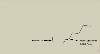
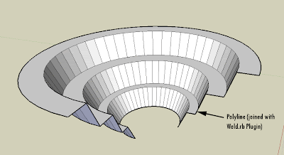
ExtrudeEdgesByLathe.rb by TIG allows us to Extrude Polylines or Faces following a circular path defined by an axis and a rotation angle. The Plugin is part of a suite of several Extrusion Plugins by the same Author that can be found here. The Plugin Allows you to do the following.


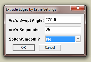
We can set all the properties of the extrusion on a dialog box that appears after we run the Plugin. These are the options for the previous example.


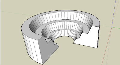
And if we select a face instead of a polyline, the plugin works too!!


Chek here how to Install SketchUp Plugins.


Show me more...