Showing posts sorted by relevance for query walls. Sort by date Show all posts

Revit: Creating a Basic Wall with Stacked Materials Using the Split Region Tool

Basic walls can behave like stacked walls in certain way if you know how to use the Split Region and Merge Tools.
Català - Castellano - Deutsch
Some walls we create might have on one side or the other a change in materials due to several reasons (some waterproofing on the lower part, a wainscoat, etc). If this happens in many walls, we mmight want to model the wall with this change of materials, and we all hate Stacked Walls. So no problem, we cana ctually do it with Basic walls and here is a step by step on how to do it in Revit.

For this example I will use a wall I am using in a project nowadays, it is made of brick as a core layer and it is finished on one side with a sort of Stucco-like material, and the other with waterproofing material. The thing is, the wall is used for a raised floor over a parkign garage, and below the level where the earth fill goes, instead of the stucco-like material, we need to have the same waterproofing we have on the other side. Since the height of this situation is fairly the same everywehere, I wanted to have the two layers (waterproofing until 1m of height and Stucco from there on). Let me show you a couple snapshots of the wall and you will see the final result.

How do we achieve this? Let's see it, the help on using the Split Region Tool found on the Revit Help gives us some hints, but not a good enought explanation as I see it. The Split Region process is a bit un-intuitive. There are two ways to achieve the same:
Option 01: Use Split Region + Assign Layers
Option 02: Create the Two Layers + Use Split Region + Merge Regions

I was going to write each step with snapshots, but I think a quick video will be moe helpful, so here it is. Sorry for the low resolution.

Hope this helps.


Show me more...

Revit: Joining Walls to Extend an Opening

If you want to model as you would build, you might find this helpful.
Català - Castellano - Deutsch
If you want to use Revit for the latest stages of design or during pre-constructio, some tools, specially those to create layer based families like Walls, Floors, Ceilings and Roofs might not work for you. This tools were probably designed to speed up modeling but thinking more of an architect's need (drafting plans) than actually Virtually Building your facility in the computer. This problem has been partially solved with the Create Parts Tool. It is a good improvement appeared in Revit 2013, but it does complicate a bit extracting quantities.

A solution to build the model as it would be build on real life is to model walls (or other layer based elements) in parts. That is, that instead of modelling a brick wall with its layers of substrates and finishes in one element, we model them in several stages.

The main problem with this approach is what to do whit openings. A Window or Door will only cut the wall that actually hosts it, right? Well, not exactly. If you have two parallel walls and place a door in one of them, you can extend the opening cut to the 2nd wall by joining geometry of the two walls. See the pic.

Simple when you know how.


Show me more...

AutoCAD: Draw Walls Using the MLINE command

Plain AutoCAD can draw walls too. You Just need to learn how.
Català - Castellano - Deutsch
AutoCAD has a pretty unknown command called MLINE that allows you to draw Multilines. Multilines are ideal for drawing walls in plain AutoCAD. You simply need to create the wall style through the MLSTYLE dialog Box and then draw the wall as you would draw a line. See the dialog box.


And a MLINE I created to represent ta wall section.


MLINE Objects do not cleanup automatically with each other like AutoCAD Architecture Walls. There is a dialog box accessible via right clicking an MLINE and selecting Multiline Edit or simply typing the command MLEDIT that will let you choose how do you want the Multilines to join/cleanup between each other. This is the dialog box.


An this is how from an uncleaned intersection between two MLINEs.


You can get a nice cleanup, in this case using the Merged T intersection.


See that to create this multiline wall I used a special linetype to represent the Insulation. You can get it for a small Paypal payment. (email delivery)


Show me more...

AutoCAD Architecture: Tutorial on Wall Cleanup Priority

Which wall style do you want to prevail over the others?
Català - Castellano
An important parameter to be able to control when working with walls in AutoCAD Architecture or ADT is the Wall Cleanup Priority. What this parameter controls is basically which wall, or which elements of a wall are going to be shown on top of others when two walls meet.
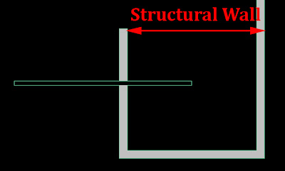
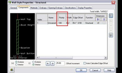
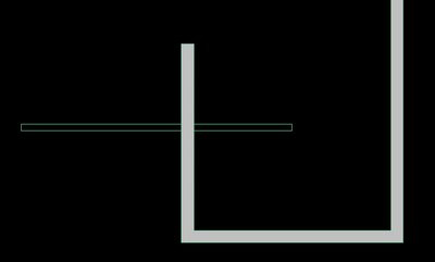
To easily understand what I mean lets see a quick example. We create a wall style that represents the Structural walls of our project with a solid fill, very simple. Then we intersect that wall with another one, we´ll use the standard style. This is the result we might get:What we actually want though is for the structural wall to be always visible since it makes no sense that a non structural wall breaks a structural one. We need to edit the wall styles. To do that we can select one of the walls, right click and go to Edit Wall Style. There we have to go to the Components Tab and be sure that the Priority of the Structural wall is lower than the priority of the Standard Wal
Once we´ve set the proper wall cleanup priorities for both wall styles, we will get the result shown below. Very easy to use.

Show me more...

Revit Architecture: Louvers in Curtain Walls

How do you create Louvers in Curtain Walls
Català - Castellano - Deutsch

A nice video on how to create Louvers on courtain walls. I am not sure if this is the optimal method, but it seems to work like a charm. It basically creates the louvers by creating a panel with a curtain wall pattern. See below.


I am trying to figure out if something similar can be done to create metal doors with louvers, will post about it.

Is this the best way to do it? Would you do it differently? Comment below, we will all benefit.

Via RevitOpEd


Show me more...

#Revit 2012: Video on the Use of the new "Create Parts"

Revit 2012 has a new feature called create parts to be able to manipulate the parts of complex elements like walls.
Català - Castellano - Deutsch
Just learned about the existence of the Twitter Autodesk account @RevitWikiHelp that provides a lot of links to useful resources on how to better use revit.

I learned about @RevitWikiHelp when they mentioned one of my posts. Now I follow them and I think they will be a great source of new Revit knowledge.

If you followed all the information on the new features of the new 2012 version of Revit, you probably know of the new "Create Parts" feature. this feature is key to work with some elements like exterior walls without the need of using complex Stacked Walls. I'll leave you with the video on this topic, which I think is good enough for you to understand the power of this feature.

Remember you can also follow the Blog using the twitter account @cadaddict where I also post short tips and retweets about Software and Processes for Construction, Architecture and Design


Show me more...

Revit: Don't Use Parts if You Want to Use Groups. Don't Use Groups if You Want to Use Parts

Exactly what the post title says. Tried it in many projects, always with problems.
Català - Castellano - Deutsch
I've been trying once again to use parts and groups together and I have been having problems as usual, not much improvement from previous releases (I am using Revit 2014). As stupid as it might seem, Revit really struggles if you break walls into parts and then group the walls in a Group that you need to repeat / rotate / mirror. The resulting parts on the copied groups behave independently from one instance of the group to the other, making it really not efficient to work with them because a lot of rework in each instance might be needed (I am working on a 30 story building, with 25 equal floors, so imagine how nice it would be if Revit could handle this properly).

I tried many different options, parts constrained, unconstrained,etc. No way Groups work efficiently as they should (as AutoCAD blocks). So my solution to solve this has been to use Groups only on relatively small elements were I don't use the create parts feature, and for the other elements (like the repeating typical floor plan) I use a linked file. I don't like it and it is also not very efficient when you have to edit it (Unload -> Open -> Save -> Reload) but it does allow me to repeat the floor where I have edited all walls using the Create Parts feature.

For more infor on what to do and what not to do with Groups check this post at AllaboutCAD.


Show me more...

Some basic CAD organization is necessary!!

You can0t work on a project with all your drawings on a single file, seriously, you are not a student anymore, and if you are, better start training for the real world.
Català - Castellano - Deutsch
I am lately working more often with BIM than I am with CAD, but recently opening and analyzing some CAD drawings recieved from an architect made me think about writing this post. The thing is, while there might be no way to organize a CAD (or BIM) project without any flaws, there are some basics that I find essential if you want to keep certain quality standards and ease of use.

If we talk about quality, there is a basic standard people should aim for, and that is about consistency of information between drawings. That is, if two walls are 6,50m apart in one drawing, the same walls should be 6,50m a part in another drawing. Does it sound too basic, well, believe me, I've seen very basic drawings not accomplishing even that. The reasons might be many, but, as I see it, you can't expect quality if you have ALL YOUR PROJECT DRAWINGS ON A SINGLE FILE AND WORK ON THIS SINGLE FILE!!
Sorry for the shouting, but this has been making me waste a lot of time.

Why would you work with all your drawings on a single file? I have no clue other than "because you haven't thought about a better way". Let's ask ourselves a few questions. If we work with all project drawings in one CAD file:
  • What happens if you want to split work amongst two people? You can't.
  • How do you check that columns, walls on other buidling elementsare on the same position in all floorplans? Well I assume you basically draw some help lines and go check if they allign, but doing this you only check in one direction...
  • What happens if you accidentally delete, loose, can't find or get a Fatal Error on your AutoCAD file? Well, instead of loosing or having to redo information about one floorplan or elevation, you might need to redo stuff in ALL your drawings
I guess I could come with even more questions that should make those who work this way stop and look for an improved process. I have work in quite big projects over the past 4 years, and none of those projects could be done having all drawings in a single file.
If you are an All Drawings in One File (ADIOF) Architect, maybe you think your projects are small enough to not require a file organization standard, well you are wrong. Any project works better if you split files. My little list for ADIOF Architects of what you could do as a minimum to increase quality and workability of your drawaing standards:
  • One file, one drawing: Anytime corrections need to be done you could have more than one people working on it
  • All floor plan drawings are on the same position in each drawing: this way you can easily use the other drawings as XREFs (External References)to check the consistency between them (the same way you would have done long ago putting one drawing on top of the other using transparent paper)
  • Use the same prefix for all files of the same sort (FL for Floor plans, EL for elevations, etc): This way your project folder will be organised by type of drawing.
  • Use a single file inserted as an External Reference for those elements such as column grids, elevator cores, stairs, etc that go vertically through the building: instead of modifying those elements once in each drawing, you will save time by changing them once only.
I think only with this 4 points, a project can start being something more workable, and checking consistency between drawings is simplified quite a lot. There are many more ways to improve how people work with CAD, but this came to me as the most basic file organization points everyone should follow.

Show me more...

Revit: Calculating and Scheduling Gross Wall Area

Revit wall area is incorrect if you want it including the openings area. This add in allows you to get the gross area (including openings) correct.
Català - Castellano - Deutsch
The way Revit calculates wall areas that have openings (doors, windows, etc) in them is by giving you the wall area minus the opening area. While this might be of some use, if actually you need to get accurate quantities I doubt this will do. The way the areas of the walls should be quantified according to, at least, our local standards is by including the opening areas that are below certain sq meters. Revit can't give you that by default (as far as I know) it just gives you the wall area minus the openings, see the example:

We need to be able to schedule the area of those openings (hello Autodesk??). Recently found an Addin, that allows to do that. It is called AutodeskWallOpeningArea (updated link)and gives you the chance to get this done right. After downloading it and installing it (simply run the .msi file) you will have a new button on your Add-ins tab in the Revit Ribon:

Once installed, simply go to a 3D view and click on the button. It will add 2 shared parameters on your wall families that will account for the openings Area.

The results you get are divided according to an area value you can set. All the openings below that Maximum value are stored as Opening Area Smaller Max, and the total openings area are added to the Opening Area Parameter. Now, you can schedule this parameters and get the Gross area of the wall by playing with calculated parameters. In this case I simply Added wall Ara + Opening Area to get the Gross Total that would be used on a project estimate.

Problems and limitations:
  1. The parameters are not dynamically updated, which means that the command must be executed in order to updated the parameter value. Is is a major problem, actually and goes completelya gains the BIM approach of an integrated database, let's be serious, this sucks badly.
  2. The Addin must be executed from a 3D view with all relevant elements (walls, doors, windows, openings, etc) visible. Second Major HUGE flaw.

Show me more...

Revit Families: what are they and how to custom create them.

A recap of what are Revit families and how to use them and custom create them.
Show me more...

AutoCAD Architecture: Irregular Walls - Endcap Tutorial

Learn how to use Endcaps. They are very useful when you want your wall openings to be more than just a square.
Català - Castellano
We have been designing a "not very modern" type of building (to say something) in the office. One of the things we have to deal with is the fact that this Gothic-Art Decoish building will have heavy pilasters on the façade to resemble some sort of old architecture.
In previous phases of the project we had been just using regular walls and adding the extra depth of the pilasters with an AEC polygon. Since we were printing with both wall boundary and wall hatch in black, that worked good enough for representation, but it was a pain in the ass when editing the wall, moving windows,etc.
On the current phase, we are reverting to a different kind of representation following more the standards set in the office. This means black boundry line + grey hatch for the wall. The problem is that if we use a regular wall and we add a AEC Polygon to the outside of it to get the extra thickness needed, we will see the line separating the wall and the AECP, and we do not want that.
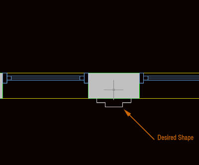
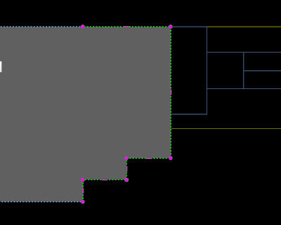
The solution I found for this problem is to use the Wall Endcaps. But let´s start first with a picture of what we want to achieve.


As you see, we have a regular wall and some windows, but we want the space between the windows (what is the name in English for that?) to have the shape of the white line. To do that, we first increase the thickness of the wall to reach the thicker point necessary. THen we select the wall, right mouse click and select Endcaps --> Edit in Place. We will access the endcap edit mode. Endcaps work exactly as AEC Polygons, so take a look at this post on how to edit AEC Polygons. In the image below you can see the endcap after being edited in the Endcap Edit in Place Mode.


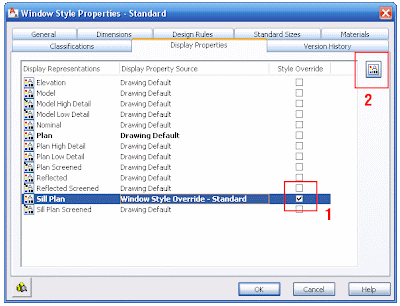
But when we exit, we see that the Window sill is showing like floating (this is because the window sill is showing the actual thickness of the wall). We have to edit the window style to fix this. Right click the window --> Edit window Style (if you just want to edit one window of this style you can pick "Edit Object Display")


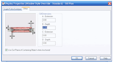
In this dialog, we have to edit the Sill Plan. Click on the box to the right of the Sill Plan and go to Edit Display Properties on the upper right. In the following dialog we need to click the "other" tab. Here is where we will set how much we want the Sill to be recessed from the wall edge to show the way we want it. In our example we need to set the B dimension to -0.10 (negative will make the sill be recessed)


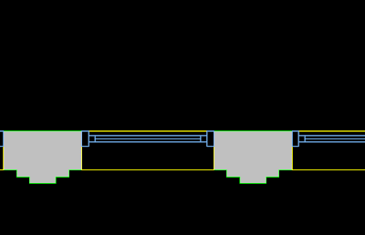
The final result is the desired. See the image below for the final wall with its irregular shape and the sill aligned to where we wanted.


Show me more...

Revit Basics: Hide and Unhide Objects

How do you hide and/or unhide walls or other objects
Català - Castellano - Deutsch
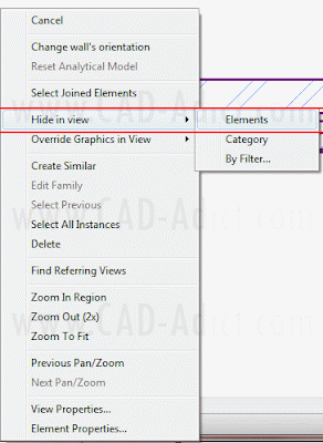
I wanted to hide a wall to be able to see the imported linework below. This took no effort to find out. Simply select the element you want to hide, right click and select Hide --> Element on the right click menu. (it can also be accessed via Ribbon)


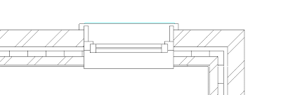
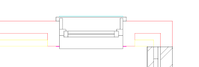
See the Element i wanted to Hide, the Wall, and once hidden how I can see the linework imported.


To Unhide Wall, Windows or any other Elements Hidden we need to activate the "Reveal Hidden Elements Button. It is on the lower left of the view.


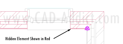
This will alow us to enter the Hidden Element Reveal interface, where hidden Elements are shown in Redish color and others are faded in Grey.


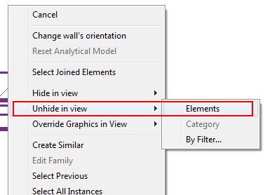
Then selecting the element and using the right click menu, or using the button on the ribbon, we can unhide them.


The same procedure can be done hiding elements by category instead of single ones, or using filters. We will see that on another post.


Show me more...

Rhino Plugins: VisualArq - Architectural Tools for Rhino

Need some ACA like tools when using Rhino? This might be the Plugin you are looking for.
Català - Castellano - Deutsch
Rhino is a great modeling software, but you will agree with me that when it comes to simple tasks like creating Walls, windows, Stairs, etc. it is not as efficient as AutoCAD Architecture or SketchUp (specially if you have the 1001bit tools Plugin).
Well that might change if you add to your set of Plugins the VisualArq set of Architectural Tools. This set of tools aims to improve the work speed for Architects, Interior Designers, Etc by adding a set of Parametric Architectural Objects and Documentation Tools.
I haven't had the chance to check it since I only have access to Rhino at work, but from the Gallery on the VisualArq website, the Plugin looks promising.
You will need Rhino's Service Release 5 to be able to use this plugin.

Show me more...

New Version of VisualARQ Architectural Tools for Rhino

New Version of VisualARQ for Rhino.
Català - Castellano - Deutsch
The friends from VisualARQ just sent me an email with the news that a new version of their Architectural Tools for Rhino is now available. VisualARQ is a set of tools that for what I have seen and read seem to turn Rhino into a more "Architectural Representation Friendly" software if that term exists.

The Tools allow Rhino to identify objects as windows, walls, etc. Much like regular BIM packages do. See a description of features here. The new features in version 1.2 can be found following this link.

In short, the new features are:
  • Beam object
  • Context help
  • IFC 2×3 export
  • Plan visibility can be specified per object depending on its position on the level.

Did I say BIM like objects? IFC 2x3 support? Well here you go BIM scheptical people. Even Freeformparadise (that would be Rhino) seems to need BIM standards objects and interoperability. The BIM steamroller is unstoppable...remember Stuart Brand's Quote "Once a new technology rolls over you, if you're not part of the steamroller, you're part of the road". What will you choose?


Show me more...

Using Layers in SketchUp: A Step-by-Step Guide

Do you use Layers in SketchUp? Maybe this will help you do it better.
Show me more...

AutoCAD: Select all Connected Geometry.

Wonder how to select with a single click all connected geometry? AutoCAD can do it, you just need to know the right command.
Català - Castellano - Deutsch
Usually my day at work involves designing and drawing both in AutoCAD and SketchUp (and eventually in Rhino depending on the complexity of the geometry of the project). Switching back and forth from one software to another makes you miss on one program some of the functions that the other program has. This was the case of the "Select all Connected" option in SketchUp. It is so useful to select all connected geometry (it can be accessed through a right click menu or by triple clicking any line on the drawing). But can something similar be done in AutoCAD? The answer is yes.

There is an Express Tool for AutoCAD called FASTSEL (accessible also via the FS shortcut) that allows us to select all the geometry that is connected (touching) any element on our drawing. The elements that can be used using this commands are LINE, POLYLINE, LWPOLYLINE, CIRCLE, ARC, ATTDEF, TEXT, MTEXT, ELLIPSE, SPLINE or IMAGE objects. BLOCKS or XREFs containing these objects will also work.
AEC Objects from some of the vertical products such as Walls or AEC Polygons are not supported. In case you have a Block or XREF containing both supported and unsupported elements, the command will only use the supported elements.

The command can be accessed transparently while using other commands by typing 'FS while the command is running. Also, use the FSMODE System Variable to control if the FS command selects all connected geometry (FSMODE = ON) or only the geometry connected to the first object (FSMODE = OFF).

Note that this Express Tool Command is mostly intended for 2D since I tried to use it in 3D and lines that are actually not touching other geometry did get connected. I find it specially useful when I accidentally explode polylines, with this command you can select all the lines that where previously connected with a single click. Select faster than a private jet with this express tool!

Show me more...

AutoCAD: Dealing with Ellipses

Ellipses are necessary but troublesome. Learn to deal with them appropriately.
Català - Castellano
If you have a Boss like mine who loves ellipse shaped Buildings, Drop-offs, Piazzas, etc. you probably have to deal with ellipses more than you wish. Ellipses are quite troublesome.
First of all they don't offset as ellipses, rather when we offset an ellipse the parallel geometry obtained is a SPLINE. Splines have the disadvantage that they can only be trimmed but not extended.

One way to partially solve this problem is to know the PELLIPSE system variable. The default value of this paramter is 0, which means ellipses are drawn as ellipses. If we set it to 1, instead of an ellipse the geometry drawn is a POLYLINE. The advantage of using polylines is that they can be exploded (Ellipses can't) and when offset they remain polylines. Another advantage is that Polylines can be converted to other types of objects (in ACA you can convert them to Walls, Spaces, etc).
The disadvantage of drawing ellipses as Polylines is that since they are an approximation of an ellipse made with multiple curved segments, if we trim part of the ellipse shaped polyline we will probably not going to be able to recover the old geometry by using the extend command.
Another consideration when deciding if you want to set PELLIPSE to 1 or 0 is to think if you will need to modify that ellipse often. If you will be trimming and extending segments of an ellipse my recommendation is to keep it in 0 (the ellipse is a "smart object" you will be able to recover all of its geometry from its smallest segment if is a real ellipse, if it is a polyline yo will have to redraw it) If you will be offsetting the ellipse better set it to 1 so you avoid getting Splines that will leave you with no flexibility.
Another issue I found when dealing with ellipses is when I want to redraw one that is not aligned with the active UCS. For some reason the "UCS Object" feature doesn't allign properly with the axis of ellipses. So, if you want to draw an ellipse using the same alignment for its axis as a previous one this is what you need to do.
You need to know the concept of Quadrant Osnap. In ellipses (and circles) quadrant osnap is a point on the ellipse that intersects the ellipse axis. See the three images below for a clearer explanation (click on the image to enlarge)

The image on the left shows a selected ellipse. The grips we see correspond to the centre and quadrant osnaps of the ellipse that we will use to get the righ UCS alignment. The image in the middle shows how we can access the Osnap contextual menu to select the quadrant osnap. (follow this link for more info on the topic). The image on the right shows the line from quadrant to quadrant drawn. We will use the align UCS to Object to this line to get the correct UCS that will allow us to redraw an ellipse equal or parallel to the original one.(This only works with Ellipses drawn with PELLIPSE = 0).

Show me more...

SketchUp Plugins: Create Custom Windows / Curtain Walls

Easily create Windows with a Plugin that works as good as windowizer but that will do any window shape or custom design.
Català - Castellano - Deutsch
I wrote not so long ago about Rick Wilson´s Windowizer Plugin to create Windows from a face. Windowizer is great, but it only creates windows based on a regular grid (number of rows - number of columns).
TIG's Latticeizer (Laticeizer.rb) does what Windowizer 3.0 can't. It creates a window with it's mullions and glass parts from a series of faces, cleaning up the intersections very neatly. See how from this set of faces (all faces have to be coplanar) i easily created a custom window.


All faces need to be coplanar and need to be Grouped. The dialog Box will let yo choose the settings, sizes, colors, etc. Pretty Cool. Thanks TIG!!


Download the Plugin Here.

Show me more...